— 24 —
4-3. RGB AMP, Sub bright adjustment
1. Adjustment procedure
• Make sure
VCC5 (CP344) = 5.0 ± 0.05 [V]
VCC15 (CP391) = 15.0 ± 0.45 [V]
VCC7 (CP390) = 8.0 ± 0.05 [V]
VCC3 (CP220) = 3.3 ± 0.08 [V]
2. Preparation
• AC adaptor or voltage regulator
• Frequency counter
3. Adjustment and checking
(1) Turn the power on while pressing SHIFT and MENU keys simultaneously. (TEST MODE)
(2) Push SHIFT ➜ SHIFT ➜ MENU keys in order rapidly. (TEST MODE 1)
(3) Select GRAY SCALE (10STEP) and execute.
(4) Apply VCC5-1 (CP362) on the killer terminal (CP308) via 22k ohm resistor.
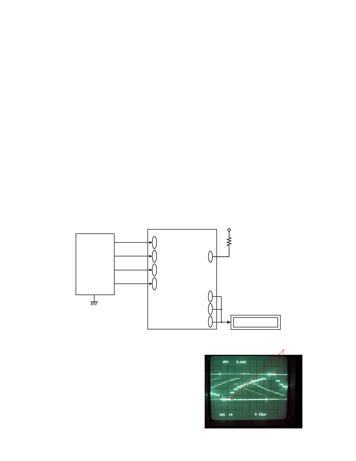
(5) Trigger VB waveform (CP322) by FRP (CP305) signal to adjust as noted below.
(6) Adjust RGB-AMP VR (VR302) so that VG waveform (CP322)’s pedestal-pedestal voltage is 4.30
± 0.05 Vp-p.
(7) Adjust SUB R BRIGHT VR (VR305) so that VR waveform (CP320)’s pedestal-pedestal voltage is 4.30
± 0.05 Vp-p.
(8) Adjust SUB B BRIGHT VR (VR304) so that VB waveform (CP324)’s pedestal-pedestal voltage is 4.20
± 0.05 Vp-p.
* Make sure that waveforms are not distorted.
* Proceed to CONTRAST, BRIGHT adjustments.
D-PCB
VR(CP320)
VB(CP324)
VG(CP322)
VCC15
(CP391)
VCC5
(CP344)
VCC7
(CP390)
VCC3
(CP220)
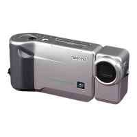
QV-3500EX
Digital oscilloscope
Figure 3-1
Killer terminal
(CP308)
VCC5-1
22KΩ
Power
Supply
4.30 ± 0.05 or 4.20 ± 0.05V
(pedestal-pedestal)
3-1
 Loading...