— 25 —
4-4. Contrast, Bright adjustments
1. Adjustment procedure
• Make sure
VCC5 (CP344) = 5.0 ± 0.05 [V]
VCC15 (CP391) = 15.0 ± 0.45 [V]
VCC7 (CP390) = 8.0 ± 0.05 [V]
VCC3 (CP220) = 3.3 ± 0.08 [V]
• RGB AMP and SUB BRIGHT adjustments should be completed (proceed from those adjustments.)
2. Preparation
• AC adaptor or voltage regulator
• Frequency counter
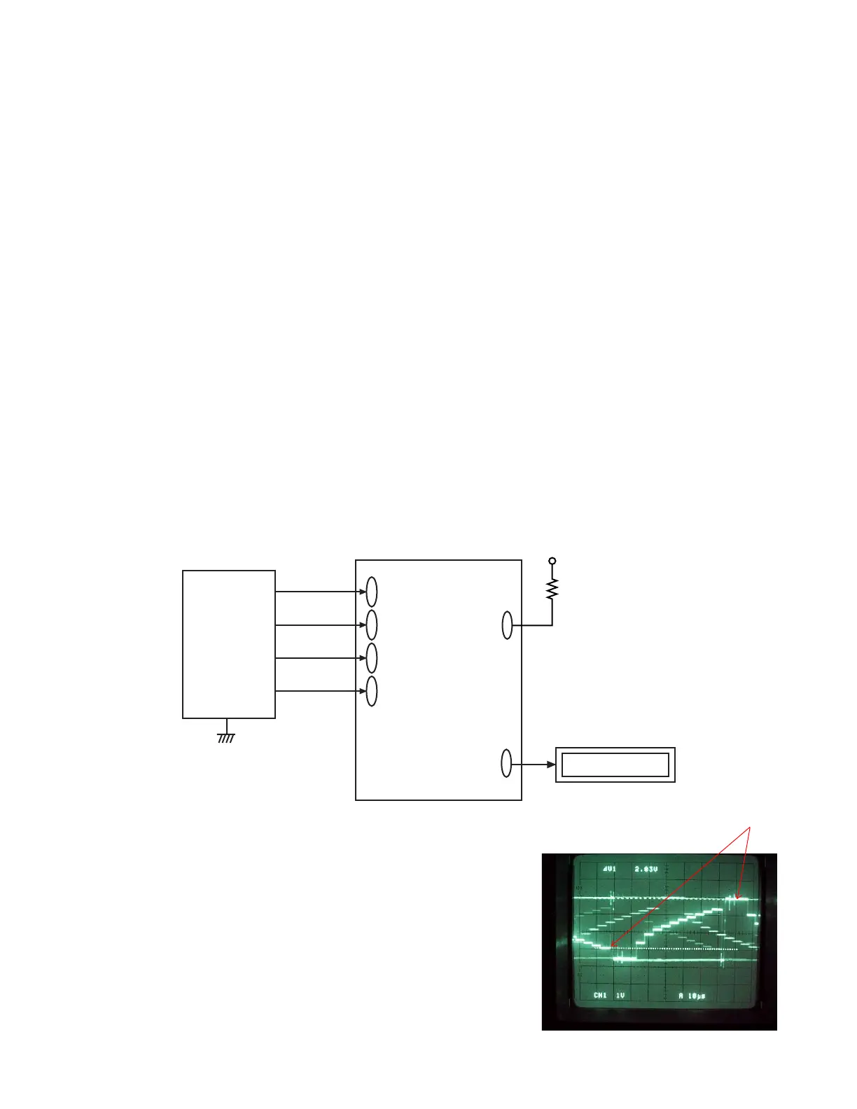
3. Adjustment and checking
(1) Turn the power on while pressing SHIFT and MENU keys simultaneously. (TEST MODE)
(2) Push SHIFT ➜ SHIFT ➜ MENU keys in order rapidly. (TEST MODE 1)
(3) Select GRAY SCALE (10STEP) and execute.
(4) Apply VCC2-1 (CP344) on the killer terminal (CP308) via 22k ohm resistor.
(5) Trigger VB waveform (CP322) by FRP (CP305) signal to adjust as noted below.
(6) Adjust contrast VR (VR306) so that contrast terminal voltage (CP306) is 1.50 ± 0.05 V temporary.
(7) Adjust Bright VR (VR303) so that pedestal-4th step is 2.45 ± 0.05Vp-p.
(8) Adjust Contrast VR (VR306) so that pedestal-10th step (white 100 %) is 2.90 ± 0.05Vp-p.
(9) After the adjustment, remove the 22k ohm resistor between killer terminal (CP308) and VCC5-1 (CP362).
* Make sure that waveforms are not distorted.
D-PCB
VCC15
(CP391)
VCC5
(CP344)
VCC7
(CP390)
VCC3
(CP220)
VG(CP322)
QV-3500EX
VCC5-1
Digital oscilloscope
Figure 3-2
22KΩ
Power
Supply
Killer terminal
(CP308)
3-2
2.90 ± 0.05 V
(pedestal-10 step)
 Loading...