
 Loading...
Do you have a question about the Chevrolet Sail 2010 and is the answer not in the manual?
| Brand | Chevrolet |
|---|---|
| Model | Sail 2010 |
| Category | Automobile |
| Language | English |
Methods for identifying vehicle VIN code and nameplate.
Table detailing vehicle specifications and optional equipment fitment.
Identification methods for engine labels and serial numbers.
Specifications for engine oil, spark plugs, and ignition systems.
Diagrams for 1.2L LMU and 1.4L LCU engine components: cylinder head, block, manifold, timing.
Procedures for engine timing calibration and valve clearance adjustment.
Overview of ECM inputs, outputs, EGR valve, programming, and idle program.
Schematic diagrams for various engine systems and components.
Methods for identifying transmission assembly codes and part numbers.
Specifications for transmission oil type, grade, and volume.
Technical specifications for SH63-MT and SH63A-MT transmissions.
Diagrams and component lists for transmission housings and gear units.
Procedure for checking and maintaining the transmission oil level.
Details on the position and assembly of the vehicle speed sensor.
Procedure for adjusting front and rear side windows.
Steps to adjust the outer front door handle lever and stroke.
Steps to adjust the outer rear door handle lever and stroke.
Overview of data link connector features and communication protocols: UART and Keyword 2000.
Procedure for entering the security code to restore audio system functions.
Information on selecting the correct area code for the audio system.
Schematic diagrams for various electrical appliances and systems.
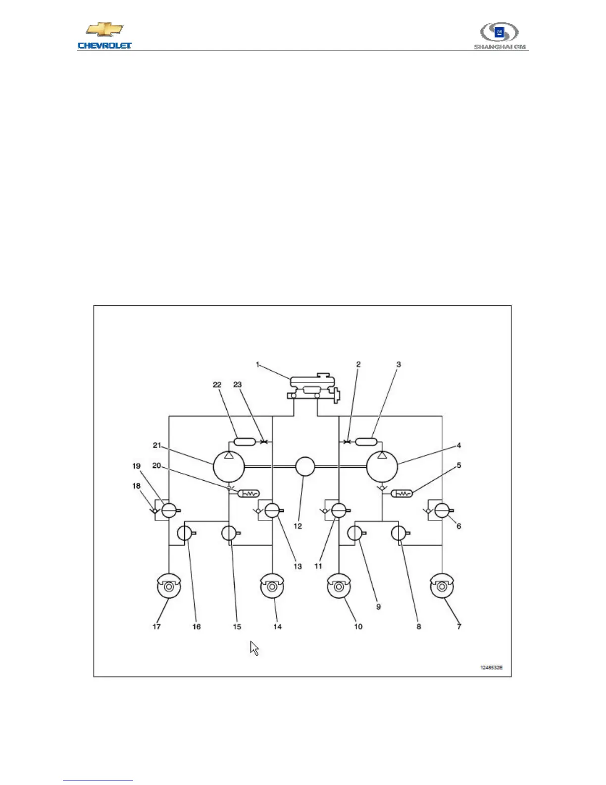
Oil circuit diagram for the MGH-25 Anti-lock Braking System (ABS).
Introduction to the MGH-25 ABS system components and functions.
Explanation of ABS operation modes.
Explanation of the normal braking mode for the ABS system.
Describes the ABS connection mode and fluid pressure application.
Explains ABS maintenance mode for stability and oil pressure.
Details ABS separation mode for wheel slip detection and pressure reduction.
Explanation of the DDRP system for vehicle stability during braking.
Functions and operation of the Electronic Brake Control Module (EBCM).
Explains the function of the solenoid valve relay in the ABS system.
Details the wheel speed sensor and its role in transmitting rotation speed.
Explains the function and conditions for the ABS warning light.
Explains the function of the brake warning light and its triggers.
Description of the rear drum brake assembly and its operation.
Procedures for adjusting drum brakes, including precautions.
Procedure for wear-in of new brake shoes and drums.
Detailed steps for bleeding the hydraulic braking system.
Procedure for adjusting the hand brake.
Schematic diagrams for various braking system circuits.
Specifications for power steering system, including oil capacity and type.
Diagrams and component lists for power steering system components.
Procedure for bleeding air from the power steering system.
Specifications for front and rear suspension types.
Diagrams and component lists for suspension system components.
Identification and overview of the MDI (Module Diagnostic Interface) device.