1-10
Cisco 12000 Series Router SIP and SPA Hardware Installation Guide
Release 12.0(32)SY1, OL-8831-01, Rev. G6, July 19, 2007
Chapter 1 Overview: Cisco 12000 Series Router SPA Interface Processors
Cisco 12000 SIP-600 Overview
SPA Interface Addresses on the Cisco 12000 SIP-600
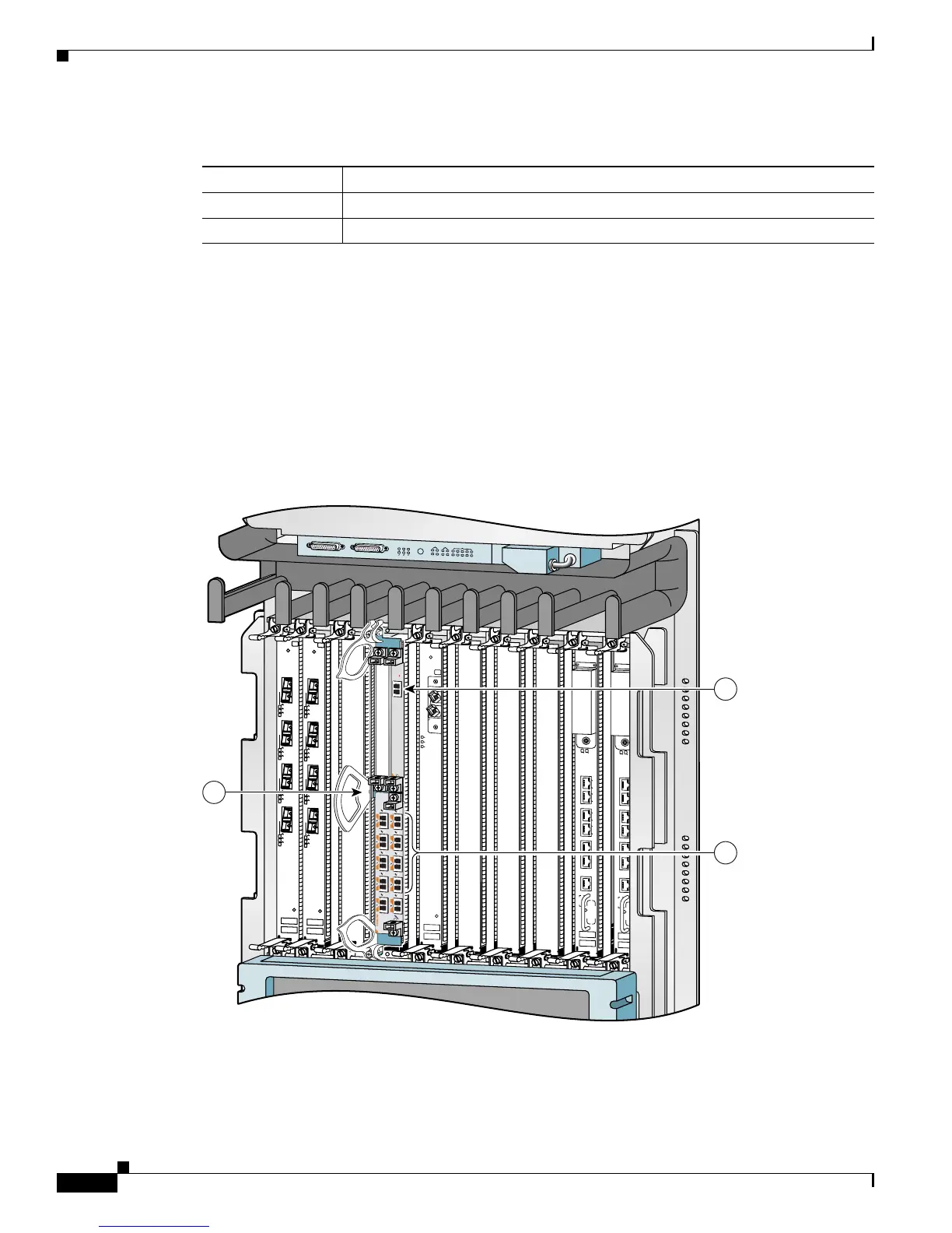
A Cisco 12000 Series Router identifies a SPA interface address by its SIP slot number, SPA subslot, and
port number on the SPA, in the format slot/subslot/port. Subslots and ports are numbered starting from
0, so each Cisco 12000 SIP-600 has two subslots 0 (left) and 1 (right). For example, the interface address
of a 1-port SPA located in the second SIP subslot, where the SIP is inserted into router line card slot 3
is 3/1/0. Figure 1-8 shows the slot, subslot, and port locations for the 1-Port 10-Gigabit Ethernet SPA
and the 10-Port Gigabit Ethernet SPA.
Figure 1-8 Slot, Subslot, and Port Locations for the 1-Port 10-Gigabit Ethernet SPA and the 10-Port
Gigabit Ethernet SPA.
Table 1-8 Subslot Locations for the 1-Port 10-Gigabit Ethernet SPA
Call Out Number Description
1Subslot 0
2Subslot 1
ACTIVE
0
CARRIER
RX PKT
ACTIVE
1
CARRIER
RX PKT
ACTIVE
2
CARRIER
RX PKT
ACTIVE
3
CARRIER
RX PKT
Q OC-3/STM-POS
ACTIVE
0
CARRIER
RX PKT
ACTIVE
1
CARRIER
RX PKT
ACTIVE
2
CARRIER
RX PKT
ACTIVE
3
CARRIER
RX PKT
Q OC-3/STM-POS
ACTIVE
CARRIER
RX PKT
OC-48/STM-16-SCPOS
EJECT
ACT
SIG
ACT
SIG
SLOT-1
SLO
T-0
CONSOLE ETH 2AUX
RESET
PERFORMANCE ROUTE PROCESSOR 2
BITS 1BITS 0
DATA
LINK
DATA
LINK
ETH 1ETH 0
EJECT
ACT
SIG
ACT
S
IG
SLOT-1
SLO
T-0
CONSOLE ETH 2AUX
RESET
PERFORMANCE ROUTE PROCESSOR 2
BITS 1BITS 0
DATA
LINK
DATA
LINK
ETH 1ETH 0
ALARM A
ALARM B
A
A
MBUS
M
IN
O
R
B
FAIL
ENABLE
M
A
J
O
R
C
R
IT
I
C
A
L
B
0
CSC
1
0
SFC
1
2
3
4
129009
ST
A
T
U
S
ACTIVE/LINK
SPA-1XTENGE-XFP-A
1
2
3
 Loading...