2-6
Cisco 12000 Series Router SIP and SPA Hardware Installation Guide
Release 12.0(32)SY1, OL-8831-01, Rev. G6, July 19, 2007
Chapter 2 Overview: Cisco 12000 Series Router Shared Port Adapters
2-Port and 4-Port Channelized T3 to DS0 SPA Overview
2-Port and 4-Port Channelized T3 to DS0 SPA Overview
The following sections describe the 2-Port and 4-Port Channelized T3 SPA:
• 2-Port and 4-Port Channelized T3 SPA LEDs, page 2-6
• 2-Port and 4-Port Channelized T3 SPA Interface Specifications, page 2-7
• 2-Port and 4-Port Channelized T3 SPA Cables and Connectors, page 2-7
2-Port and 4-Port Channelized T3 SPA LEDs
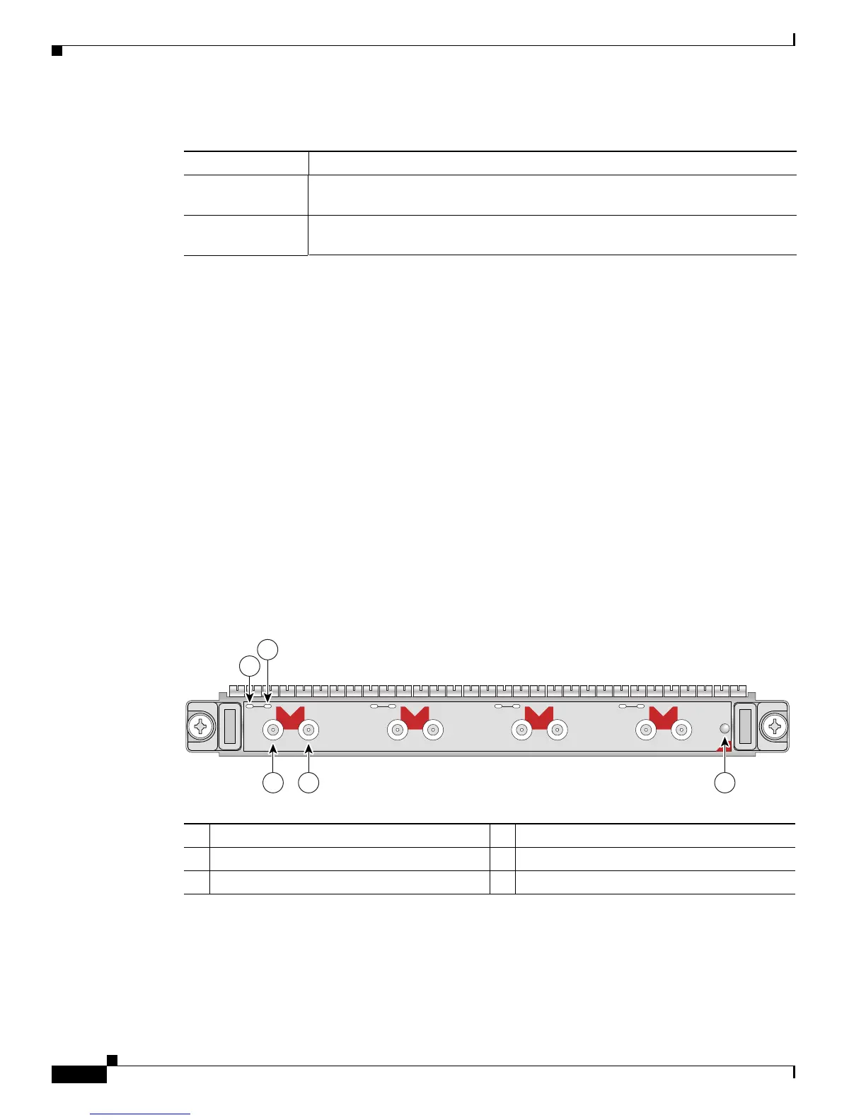
The 2-Port and 4-Port Channelized T3 SPA has three types of LEDs. There are two LEDs for each port
on the SPA, and one STATUS LED. Figure 2-2 shows an example of these LEDs on a 4-Port Channelized
T3 SPA.
Figure 2-2 4-Port Channelized T3 SPA Faceplate
Table 2-4 2-Port and 4-Port Clear Channel T3/E3 SPA Connectors
Connector Label Meaning
TX Transmitted signals appear on the center contact, and the outer shield is ground
for the 75-ohm RG-59 coaxial cable you attach to the TX BNC connector.
RX Received signals appear on the center contact, and the outer shield is ground for
the 75-ohm RG-59 coaxial cable you attach to the RX BNC connector.
1 C/A (Carrier/Alarm) LED 4 RX (Receive) connector
2 A/L (Active Loopback) LED 5 STATUS LED
3 TX (Transmit) connector
C/A
TX
RX
1
STAT US
SPA-4XCT3/DS0
0
A/L
C/A
TX
RX
A/L
C/A
TX
RX
2
A/L
C/A
TX
RX
3
A/L
1
2
3 4 5
116854
 Loading...