EasyManua.ls Logo

Cisco 12000 - Series Chassis Modular Expansion Base User Manual

Cisco 12000 - Series Chassis Modular Expansion Base
132 pages
To Next Page IconTo Next Page
To Previous Page IconTo Previous Page
Page #82 background image
2-40
Cisco 12000 Series Router SIP and SPA Hardware Installation Guide
Release 12.0(32)SY1, OL-8831-01, Rev. G6, July 19, 2007
Chapter 2 Overview: Cisco 12000 Series Router Shared Port Adapters
1-Port OC-192c/STM-64 POS RPR XFP SPA Overview
Use a single-mode optical fiber that has a modal-field diameter of 8.7 ±0.5 microns (nominal diameter
is approximately 10/125 microns) to connect your router to a network.
Figure 2-25 shows the cable type for use with the XFP optical transceiver module on the 1-Port
OC-192c/STM-64 POS/RPR XFP SPA.
Figure 2-25 LC-Type Cable for the XFP Optical Transceiver Modules
Note The 40-pin connector on the 1-Port OC-192c/STM-64 POS/RPR XFP SPA is used for resilient packet
ring (RPR) connections. This feature is not supported in Cisco IOS Release 12.0(31)S.
OC-192 Module Connections
Table 2-29 shows the OC-192 specifications for use with the 1-Port OC-192c/STM-64 POS/RPR XFP
SPA.
/ / / /
/ /
TXRX
84929
Table 2-29 OC-192 Specifications
Specification Description
Wavelength OC-192 SR-1: 1290 nm to 1330 nm
OC-192 IR-2: 1530 nm to 1565 nm
OC-192 LR-2: 1530 nm to 1565 nm
Cabling distance (maximum) OC-192 SR-1: 2 km (1.2 miles)
OC-192 IR-2: 40 km (24.8 miles)
OC-192 LR-2: 50 miles (80 km)
Operating case temperature range OC-192 SR-1: 23 to 158 degrees F (–5 to 70 degrees C)
OC-192 IR-2: 23 to 158 degrees F (–5 to 70 degrees C)
OC-192 LR-2: 23 to 158 degrees F (–5 to 70 degrees C)
Tx Power OC-192 SR-1: –6 dBm –1 dBm
OC-192 IR-2: –1 dBm +2 dBm
OC-192 LR-2: 0 to +4 dBm
Receiver Sensitivity (maximum) OC-192 SR-1: –11 dBm
OC-192 IR-2: –14 dBm
OC-192 LR-2: –24 dBm

Table of Contents

Question and Answer IconNeed help?

Do you have a question about the Cisco 12000 - Series Chassis Modular Expansion Base and is the answer not in the manual?
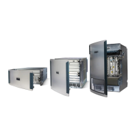
Cisco 12000 - Series Chassis Modular Expansion Base Specifications

General IconGeneral
Product FamilyCisco 12000 Series
Series12000
Form FactorRack-mountable
Chassis TypeModular Expansion Base
SlotsVaries by model (typically 4, 6, or 8 slots)
Supported Line CardsOC-3, OC-12, OC-48, OC-192, Gigabit Ethernet
Power Supply OptionsAC and DC power supplies available
RedundancyPower supply redundancy, Route Processor redundancy
CoolingMultiple redundant fans
Operating Temperature32°F to 104°F (0°C to 40°C)
Regulatory ComplianceUL
Relative Humidity5 to 95% (non-condensing)

Summary

Obtaining Technical Assistance

Cisco Technical Support & Documentation Website

Details how to access Cisco's online support resources, including documentation and tools for resolving technical issues.

CHAPTER 1: Overview: Cisco 12000 Series Router SPA Interface Processors

SIP and SPA Compatibility

Details which SPAs are supported by which SIPs and the Cisco 12000 Series Router.

Router Hardware Installation

Guides users to refer to router-specific installation guides for hardware setup and requirements.

SIP Software and Hardware Compatibility

Lists compatible Cisco IOS software releases and minimum hardware revision numbers for supported SIPs.

CHAPTER 2: Overview: Cisco 12000 Series Router Shared Port Adapters

CHAPTER 3: Preparing to Install a SPA Interface Processor or a Shared Port Adapter

Required Tools and Equipment

Lists the necessary tools and parts for installing SIPs and SPAs, including ESD prevention equipment.

Safety Guidelines

Provides general safety guidelines for working with electrical power and telephone wiring.

Laser/LED Safety

Covers safety precautions related to laser and LED emissions from optical ports and modules.

CHAPTER 4: Installing and Removing a SPA Interface Processor

Handling SIPs

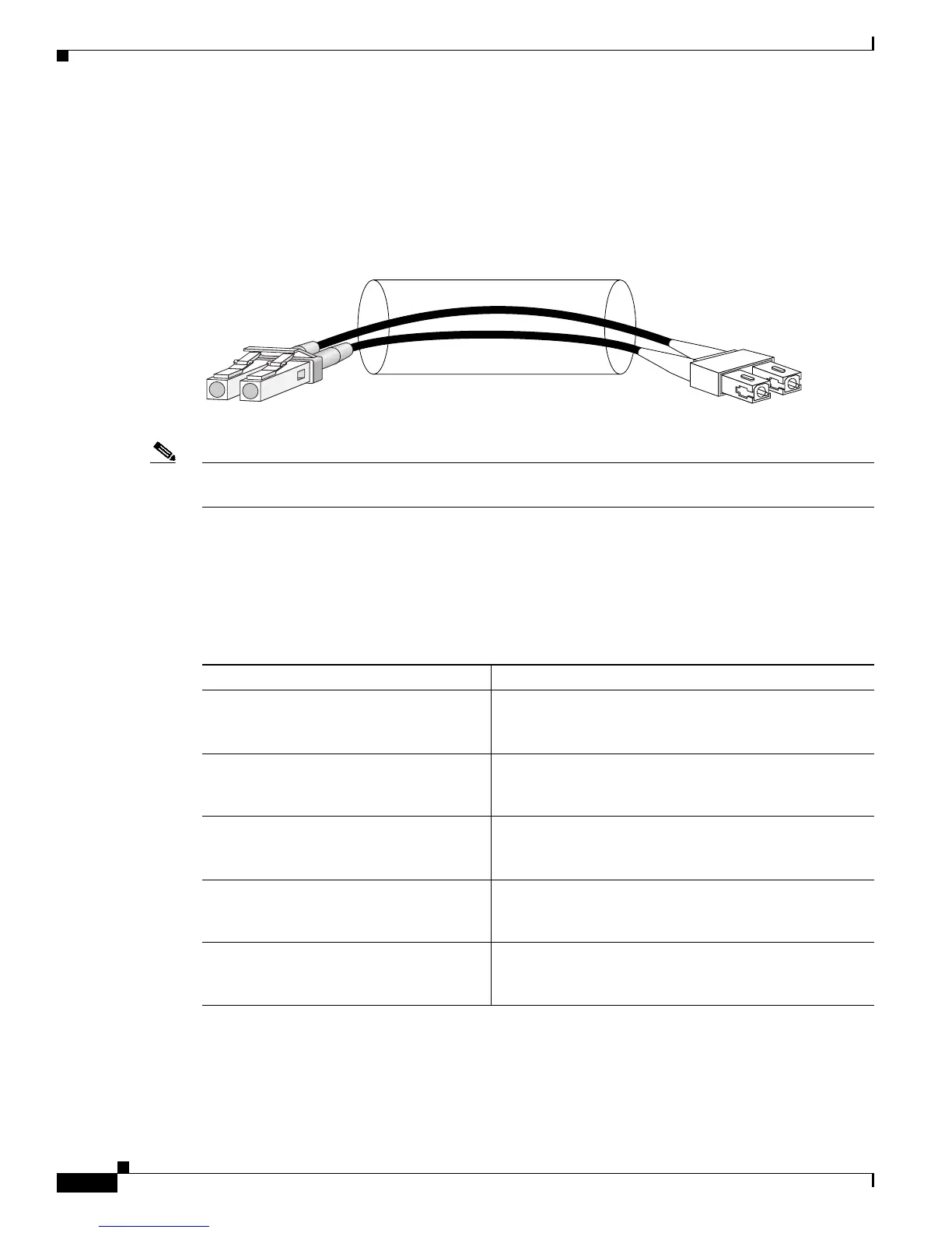
Instructs on how to safely handle SIPs, emphasizing ESD precautions and carrier edges.

Removing and Installing a SIP

Details the step-by-step procedures for removing and installing SIPs into the router.

CHAPTER 5: Installing and Removing a Shared Port Adapter

Handling SPAs

Provides guidance on safely handling SPAs, stressing ESD precautions and avoiding contact with components.

SPA Installation and Removal

Explains the step-by-step process for installing and removing SPAs within a SIP.

Checking the Installation

Details methods to verify SIP and SPA installation using console messages, LEDs, and show commands.

CHAPTER 6: Troubleshooting the Installation

Using show Commands to Check Status

Explains how to use `show` commands to display configuration, traffic, and error information for SIPs.

Advanced SIP Troubleshooting

Provides advanced troubleshooting steps for SIP failures, focusing on hardware-related issues.

Related product manuals