12
Cisco 2500 Series Wireless Controller Getting Started Guide
Installing the Controller
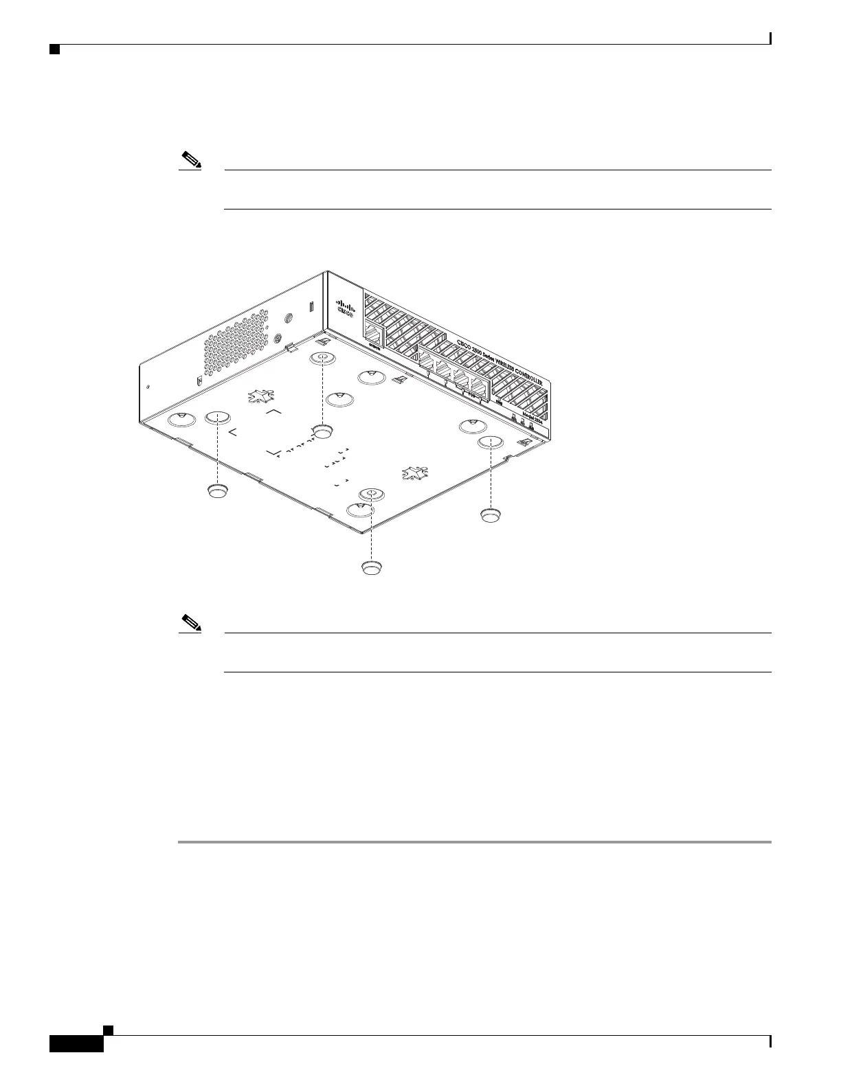
Step 2 Remove the four rubber feet from the adhesive strip and attach the feet to the recessed areas on the
bottom of the unit as shown in Figure 4.
Note We strongly recommend that you attach the rubber feet. Doing so helps prevent airflow
restriction and overheating.
Figure 4 Installing the Rubber Feet on the Bottom of the Controller
Step 3 Place the switch on the table or shelf near an AC power source.
Note Allow 3 inches of space around the controller ventilation openings to prevent airflow restriction
and overheating.
Step 4 After the controller is mounted on a shelf or desk, perform the following tasks to complete the
installation:
• Connecting the Controller Console Port
• Securing the Power Adapter Cable
• Connecting to the Network
Step 5 For configuration instructions about using the CLI setup program, see the “Running the Bootup Script
and Power-On Self Test” section on page 20.
Mounting the Controller on a Wall (Rack-Mount Brackets)
The controller can be mounted on a wall using an optional rack-mount bracket kit that is not included
with the controller. You can order a kit with 19-inch rack mounting brackets and hardware from Cisco.
The kit part number is AIR-CT2504-RMNT.

 Loading...