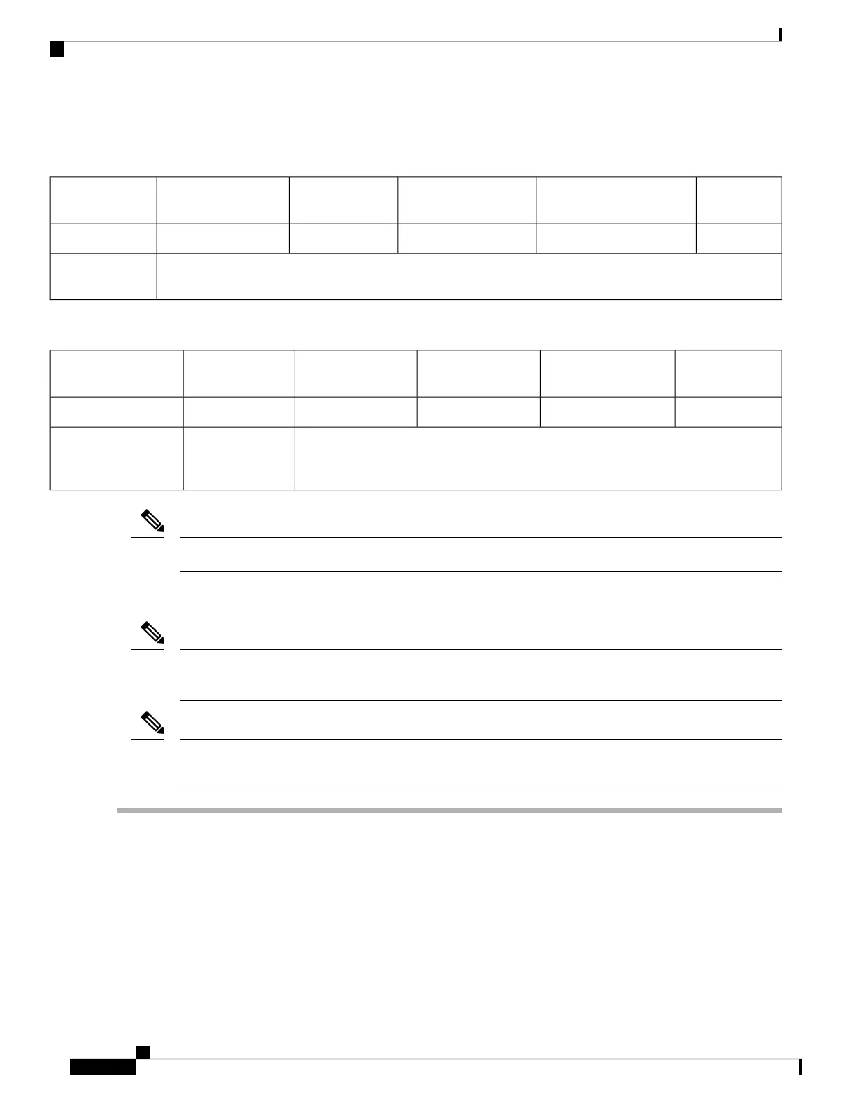
The following tables describe the specifications for the slots.
Table 6: PCIe Riser 1/Slot 1
NCSI
Support
Card Height (Rear Panel
Opening)
Maximum Card
Length
Connector
Length
Electrical Lane
Width
Slot Number
YesFull-height¾ lengthx24 connectorGen-3 x161
One socket for Micro SD cardMicro SD card
slot
Table 7: PCIe Riser 2/Slot 2
NCSI SupportCard Height (Rear
Panel Opening)
Maximum Card
Length
Connector LengthElectrical Lane
Width
Slot Number
Yes½ height½ lengthx24 connectorGen-3 x161
Other end of cable connects to front drive backplane to support front-panel NVMe
SSDs.
Gen-3 x8PCIe cable connector
for front-panel NVMe
SSDs
Riser 1/Slot 1 is not available in single-CPU configurations.
Note
Replacing a PCIe Card
If you are installing a Cisco Virtual Interface Card, there are prerequisite considerations. See Cisco Virtual
Interface Card (VIC) Considerations, on page 70.
Note
RAID controller cards install into a separate mRAID riser. See Replacing a SAS Storage Controller Card
(RAID or HBA), on page 74.
Note
Step 1 Remove an existing PCIe card (or a blank filler panel) from the PCIe riser:
a) Shut down and remove power from the server as described in Shutting Down and Removing Power From the Server,
on page 29.
b) Slide the server out the front of the rack far enough so that you can remove the top cover. You might have to detach
cables from the rear panel to provide clearance.
If you cannot safely view and access the component, remove the server from the rack.
Caution
c) Remove the top cover from the server as described in Removing the Server Top Cover, on page 30.
d) Remove any cables from the ports of the PCIe card that you are replacing.
Cisco APIC M3/L3 Server Installation and Service Guide
68
Maintaining the Server
Replacing a PCIe Card
 Loading...