GPS Port Pinout
The platform is capable of receiving or sourcing GPS signals of 1 PPS & 10 MHz. These interfaces are
provided by two mini-coax 50-Ohm, 1.0/2.3 DIN series connector on the front panel. Similarly there are two
mini-coax 50-Ohm connectors provided in the front panel to output this 1PPS and 10MHz.
The table below summarizes the GPS port pinouts.
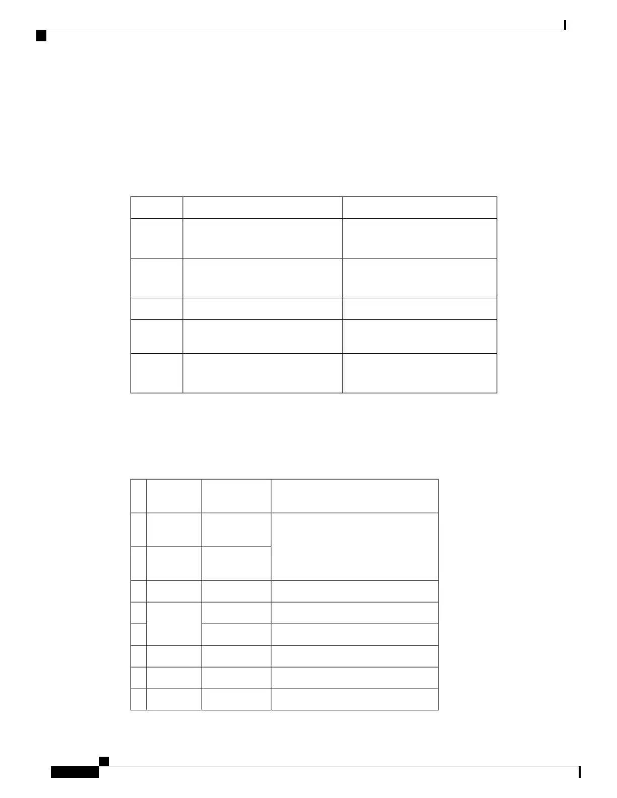
Table 15: GPS Port Pinout
1PPS (input and output)10 Mhz (input and output)
Input—Pulse shape
Output—Pulse shape
Input—Sine wave
Output—Square wave
Waveform
Input— > 2.4 volts TTL compatible
Output— > 2.4 volts TTL compatible
Input— > 1.7 volt p-p(+8 to +10 dBm)
Output— > 2.4 volts TTL compatible
Amplitude
50 ohms50 ohmsImpedance
26 microseconds50% duty cyclePulse
Width
40 nanosecondsInput—AC coupled
Output—5 nanoseconds
Rise Time
Time of Day Pinout
The table below summarizes the ToD pinouts.
Table 16: ToD pinouts
DescriptionDirectionSignal
Name
Pin
Do Not ConnectOutput or
Inputs
RESERVED1
Output or
Inputs
RESERVED2
1PPS RS422 signal
Output1PPS_N3
——GND4
——5
1PPS RS422 signal
Input1PPS_P6
Time of Day R422 output or input signalOutput or inputTOD_N7
Time of Day R422 output or input signalOutput or inputTOD_P8
Cisco ASR 907 Router Hardware Installation Guide
158
Troubleshooting
GPS Port Pinout
 Loading...


