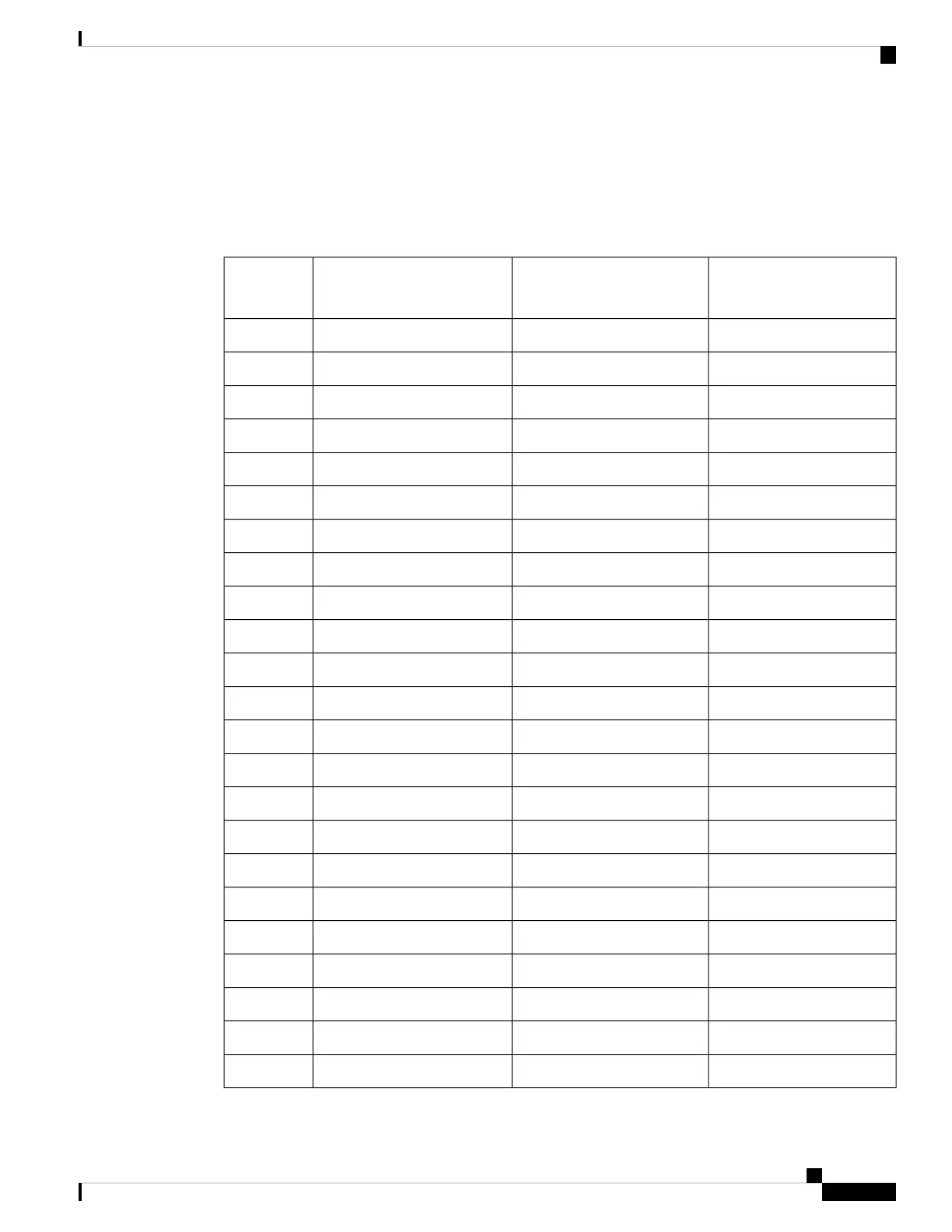
Patch Panel Pinout
The table below summarizes the patch panel pinouts of the connectors from the 48 port T1/E1 DIN, RJ48,
AMP64, and 48 port T3/E3 DIN, HDBNC connectors that connects to the interface module (IM).
Table 27: Patch Panel Pinout
Signal Name
Connector (32-47)
Signal Name
Connector (16-31)
Signal Name
Connector (0-15)
Pin
TX_PORT47_RINGTX_PORT31_RINGTX_PORT15_RING1
TX_PORT47_TIPTX_PORT31_TIPTX_PORT15_TIP2
TX_PORT46_RINGTX_PORT30_RINGTX_PORT14_RING3
TX_PORT46_TIPTX_PORT30_TIPTX_PORT14_TIP4
TX_PORT45_RINGTX_PORT29_RINGTX_PORT13_RING5
TX_PORT45_TIPTX_PORT29_TIPTX_PORT13_TIP6
TX_PORT44_RINGTX_PORT28_RINGTX_PORT12_RING7
TX_PORT44_TIPTX_PORT28_TIPTX_PORT12_TIP8
TX_PORT43_RINGTX_PORT27_RINGTX_PORT11_RING9
TX_PORT43_TIPTX_PORT27_TIPTX_PORT11_TIP10
TX_PORT42_RINGTX_PORT26_RINGTX_PORT10_RING11
TX_PORT42_TIPTX_PORT26_TIPTX_PORT10_TIP12
TX_PORT41_RINGTX_PORT25_RINGTX_PORT9_RING13
TX_PORT41_TIPTX_PORT25_TIPTX_PORT9_TIP14
TX_PORT40_RINGTX_PORT24_RINGTX_PORT8_RING15
TX_PORT40_TIPTX_PORT24_TIPTX_PORT8_TIP16
———17
———18
TX_PORT39_RINGTX_PORT23_RINGTX_PORT7_RING19
TX_PORT39_TIPTX_PORT23_TIPTX_PORT7_TIP20
TX_PORT38_RINGTX_PORT22_RINGTX_PORT6_RING21
TX_PORT38_TIPTX_PORT22_TIPTX_PORT6_TIP22
TX_PORT37_RINGTX_PORT21_RINGTX_PORT5_RING23
Cisco ASR 907 Router Hardware Installation Guide
171
Troubleshooting
Patch Panel Pinout
 Loading...


