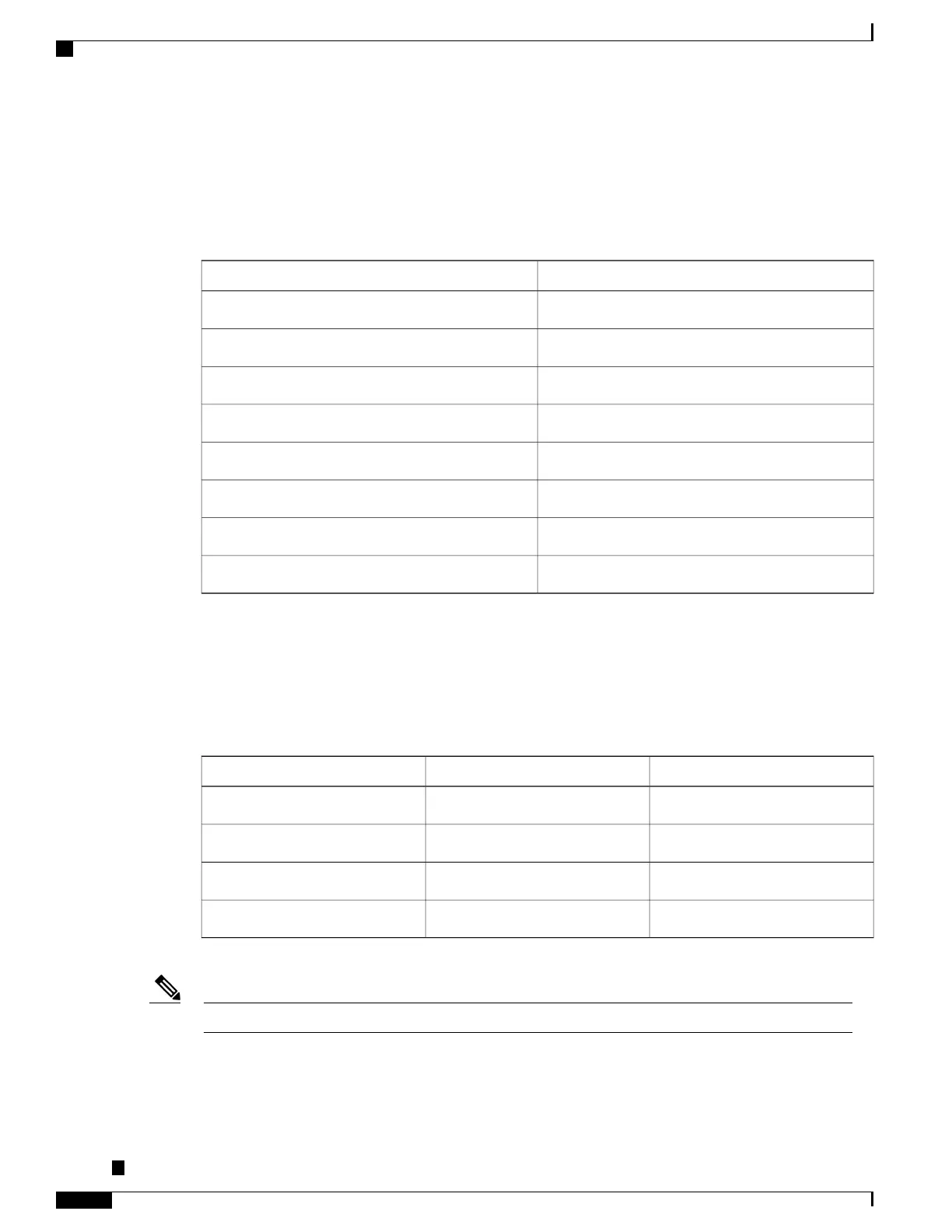
Management Ethernet Port Pinouts
The table below summarizes the Management Ethernet port pinouts.
Table 21: Fan Alarm Port Pinout
Signal NamePin
TRP0+1
TRP0-2
TRP1+3
TRP2+4
TRP2-5
TRP1-6
TRP3+7
TRP3-8
USB Console Port Pinouts
The table below summarizes the USB console port pinouts.
Table 22: Single USB Console Port Pinouts
DescriptionSignal NamePin
+5VDCVccA1
Data -D-A2
Data +D+A3
GroundGndA4
The USB console port +5VDC is input, and operates as an USB peripheral device.Note
Cisco ASR-920-24SZ-IM, ASR-920-24SZ-M, ASR-920-24TZ-M Aggregation Services Router Hardware Installation
Guide
130
Troubleshooting
Management Ethernet Port Pinouts
 Loading...


