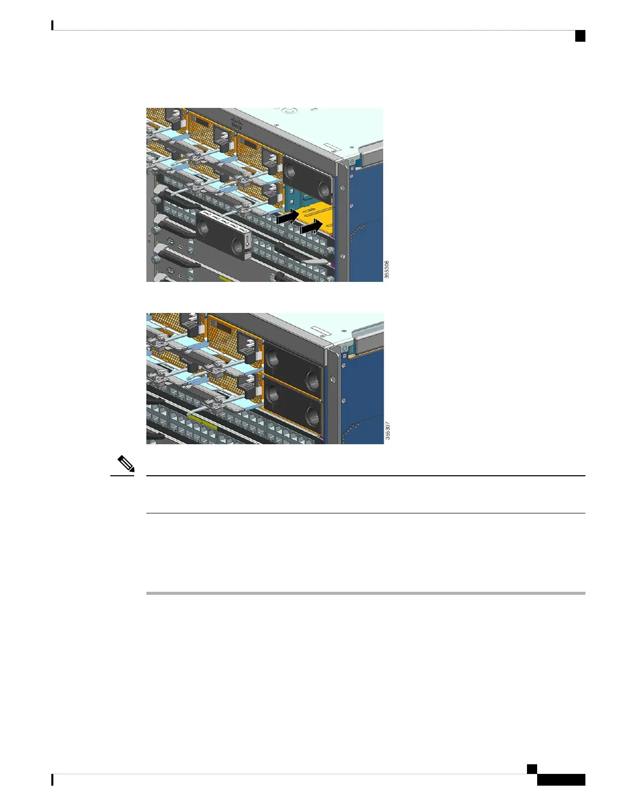
Figure 35: Installing a Power Supply Blank Cover
Figure 36: Power Supply Blank Cover Installed
Power supply blank covers can be placed in any slot when fewer than eight power supplies are installed in a
chassis.
Note
Verifying the Power Supply Module Installation
Procedure
Step 1 Verify the power supply operation by checking the power supply’s front-panel LEDs. You should see the
following:
• The INPUT LED is green.
• The OUTPUT LED is green if it is an active module and blinking green if it is a redundant module.
• The FAIL LED is off.
Cisco Catalyst 9400 Series Switches Hardware Installation Guide
127
Removing and Replacing FRUs
Verifying the Power Supply Module Installation
 Loading...