* In the illustration, the red and black cables do not interconnect. The two black
cables are connected to the same negative output of the DC source; the two red
cables are connected to the same positive output of the DC source.
Note
Cabling Requirements
When running power and data cables together in overhead cable trays or subfloor cable trays, be aware of the
following caution:
We strongly recommend that power cabling runs and other potential noise sources be located as far away as
practical from LAN cabling that terminates on Cisco equipment. In situations where this type of long parallel
cable runs exist and cannot be separated by at least 3.3 feet (1 meter), we recommend that you shield these
potential noise sources. To avoid interference, the source should be shielded by housing it in a grounded
metallic conduit.
Caution
For IEEE 802.3bt Type 4 installations, we recommend using Category 6a cables, rated at 75°C with conductors
23AWG or larger, in bundle sizes of 192 or less.
If your installation does not use the recommended cable, following are the other options that are compliant
to National Electrical Code (NEC):
• Other Category cables (like Category 5e, or Category 6 cables) rated at 75°C, with conductors 23AWG,
in bundle sizes of 192 or less.
• Limited Power (-LP) cable with 0.6A
• Cables with conductors 23AWG, rated at 60°C, in bundle sizes of 61 or less
• Cables with conductors 24AWG, rated at 75°C, in bundle sizes of 91 or less
• Cables with conductors 24AWG, rated at 60°C, in bundle sizes of 37 or less
For a detailed analysis on the recommended cabling, refer Analysis of Cabling Requirements for IEEE 802.3bt
Type 4 Devices.
Rack-Mounting Guidelines
Rack Specifications
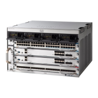
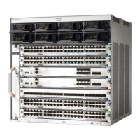
Cisco Catalyst 9400 Series Switches are designed to be installed in standard, 19-inch equipment racks that
meet EIA-310-D specifications. Before rack-mounting the chassis, ensure that the equipment rack complies
with all requirements and guidelines
Mounting Location Guidelines
Cisco Catalyst 9400 Series Switches must be front-mounted.
Cisco Catalyst 9400 Series Switches Hardware Installation Guide
41
Preparing for Installation
Cabling Requirements
