No user-serviceable parts inside. Do not open. Statement 1073
Warning
Installation of the equipment must comply with local and national electrical codes. Statement 1074
Warning
Before you begin
You may need a Phillips-head screwdriver to loosen the captive installation screws.
Procedure
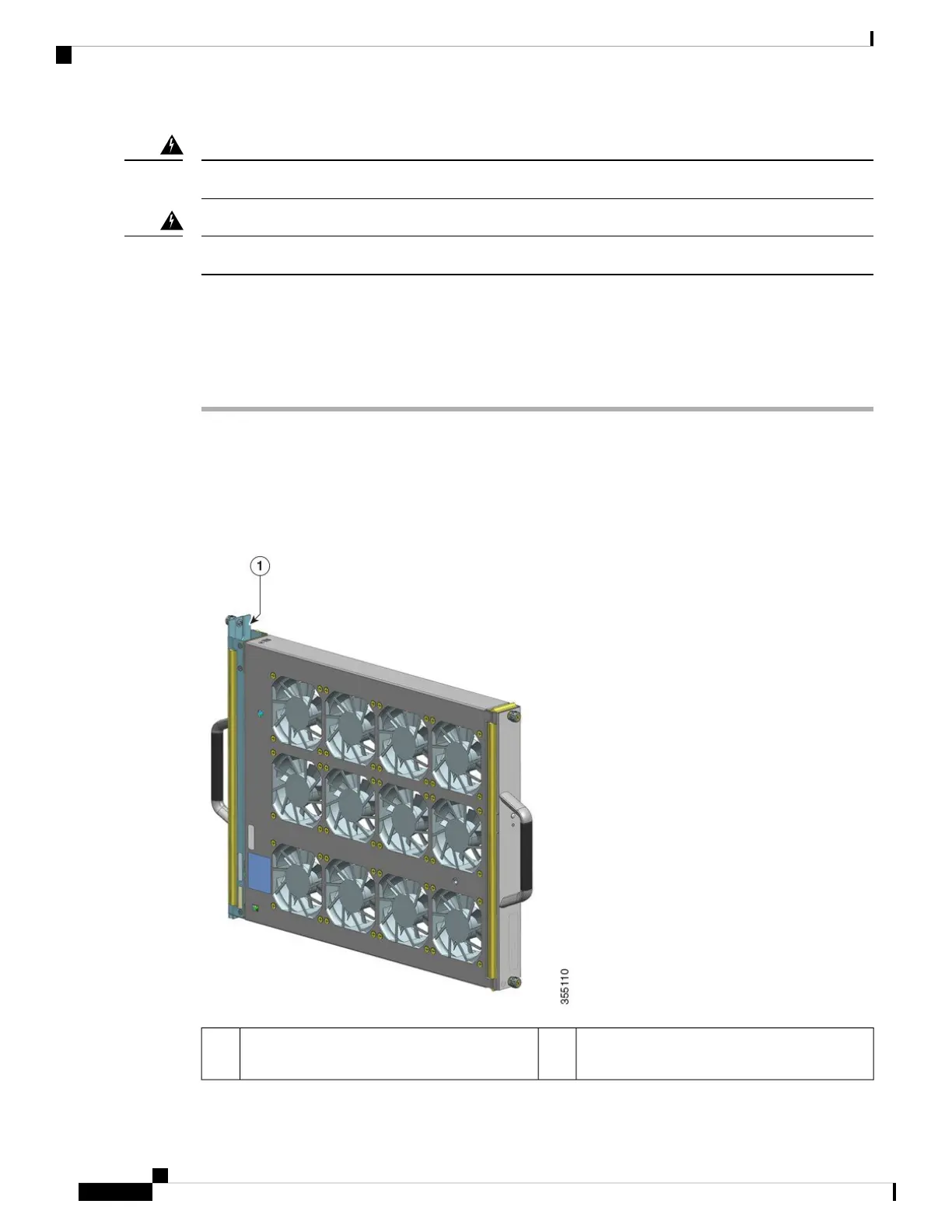
Step 1 Ready the replacement fan tray by removing it from the shipping packaging. Keep it on an anti-static mat and
within arm's reach. Do not detach the adapter module.
When you remove and replace a fan tray in a system that is powered on, there is a time constraint.
So it is important to complete this first step before you remove the fan tray from the rear of the
chassis.
Important
--Fan tray assembly, with the adapter intact and
ready for installation from the rear
1
Cisco Catalyst 9400 Series Switches Hardware Installation Guide
92
Removing and Replacing FRUs
Removing a Fan Tray from the Rear
 Loading...