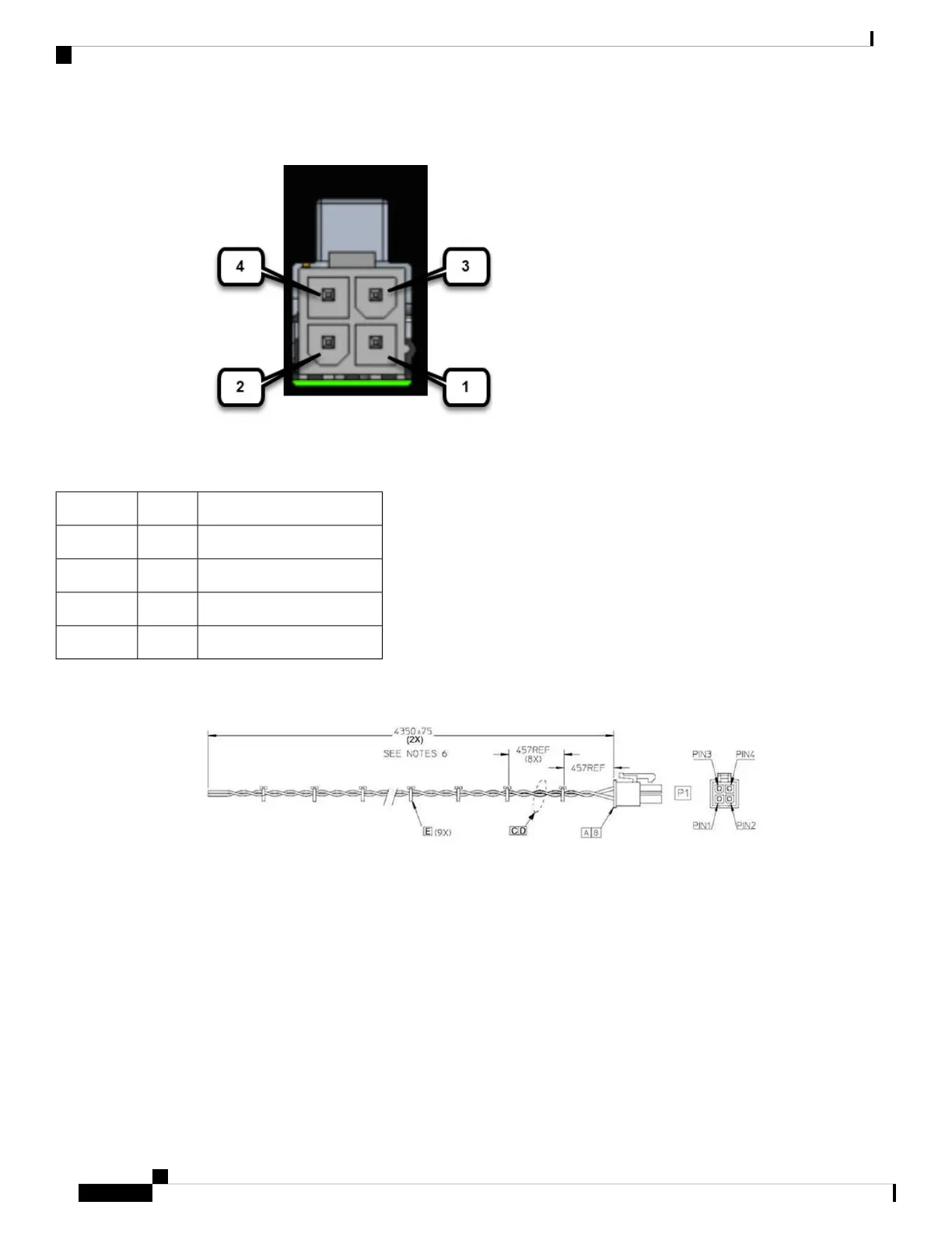
Figure 31: Power Connector Pinouts
Table 30: Power Connector Descriptions
DescriptionNamePin Number
DC Power Return (GND-)DC -1
CAN Bus Differential SignalCAN_P2
DC Power Input (12V, 24V)DC +3
CAN Bus Differential SignalCAN_N4
The IR1800 can be installed without connecting to the CAN Bus. There is a 2-wire cable that can be ordered
(CAB-PWR-15-MF4). The following is a diagram of the cable:
Verifying Connections
To verify that all the devices are properly connected to the router, turn on all the connected devices, and then
check the LEDs.
Cisco Catalyst IR1800 Rugged Series Router Hardware Installation Guide
82
Connecting the Router
Verifying Connections
 Loading...


