Front Panel
The following figure shows the front panel of the Firepower 2110 and 2120. See Front Panel LEDs, on page
12 for a description of the LEDs.
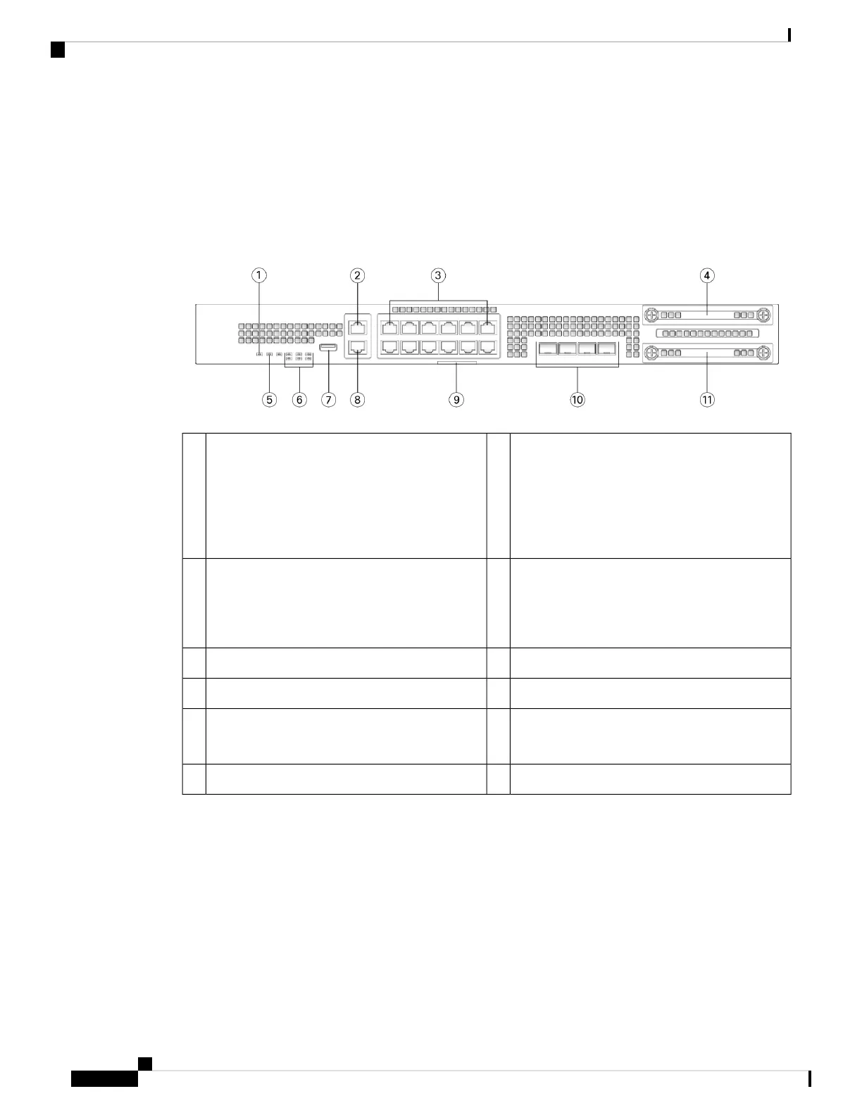
Figure 9: Firepower 2110 and 2120 Front Panel
Gigabit Ethernet management port:
• Firepower Threat Defense—Management 0
(also referred to as Management 1/1 and
Diagnostic 1/1)
• ASA—Management 1/1
2Power LED1
SSD 1 (slot 1)412 RJ-45 1 G/100 M/10 M auto duplex/auto
MDI-X Base-T ports
Ethernet 1/1 through 1/12 labeled top to bottom,
left to right
3
System LEDs6Locator LED5
RJ-45 console port8Type A USB 2.0 port7
Four fixed SFP (1 Gb) ports
Fiber ports 1/13 through 1/16 labeled left to right
10Pullout asset card with chassis serial number9
—SSD (slot 2)11
The following figure shows the front panel of the Firepower 2130 and 2140. See Front Panel LEDs, on page
12 for a description of the LEDs.
Cisco Firepower 2100 Series Hardware Installation Guide
10
Overview
Front Panel
 Loading...


