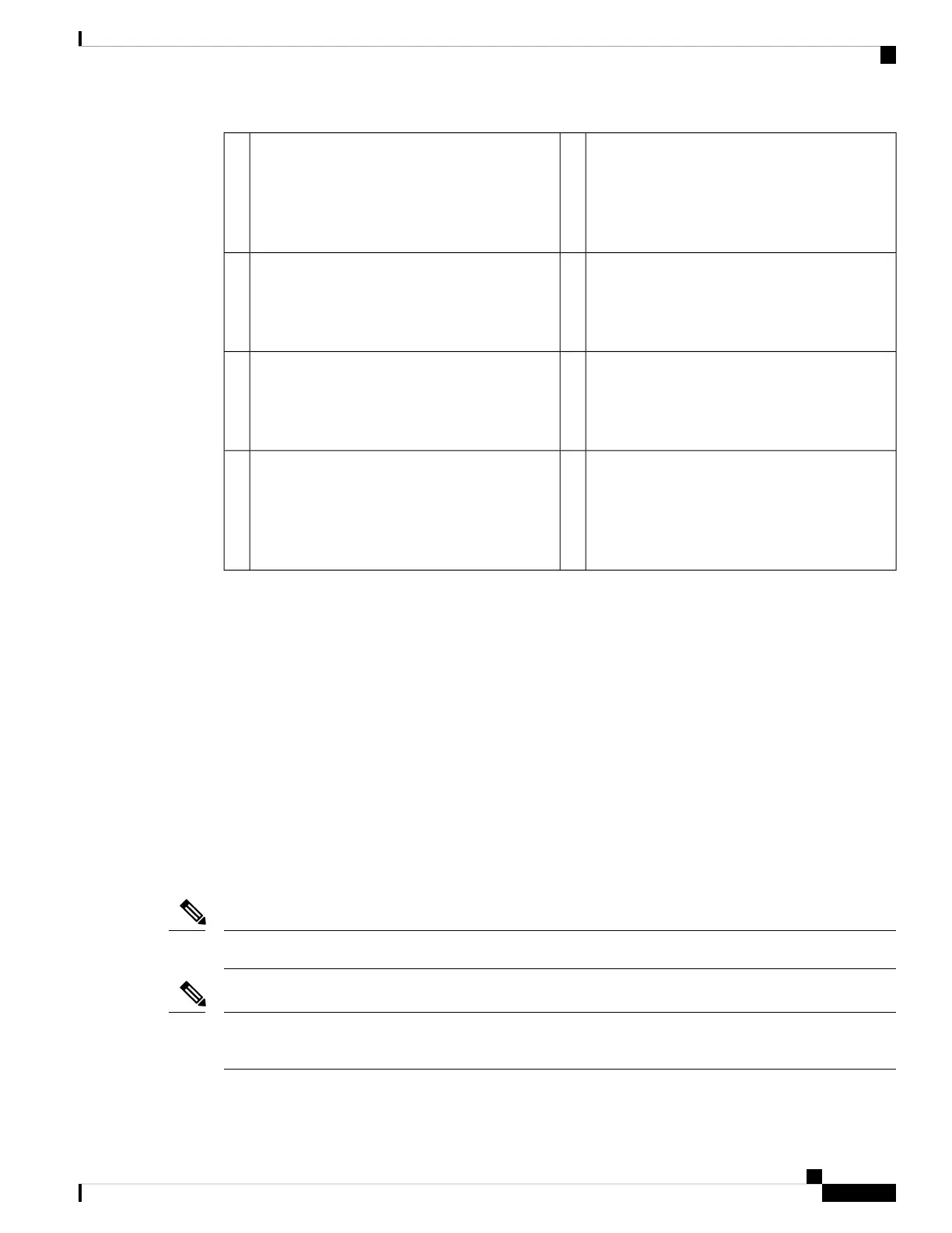
Ethernet X/1
Ports 1 and 2 are paired together to form a
hardware bypass pair. LED B1 applies to this
paired port.
2Bypass LEDs B1 through B4
• Green—In standby mode.
• Amber, flashing—Port is in hardware bypass
mode, failure event.
1
Ethernet X/2
Ports 5 and 6 are paired together to form a
hardware bypass pair. LED B3 applies to this
paired port.
4Ethernet X/2
Ports 3 and 4 are paired together to form a
hardware bypass pair. LED B2 applies to this
paired port.
3
Captive screw/handle6Ethernet X/2
Ports 7 and 8 are paired together to form a
hardware bypass pair. LED B4 applies to this
paired port.
5
—Network activity LEDs
• Left LED—Green indicates network activity
when a 10M/100M/1G connection is made.
• Right LED—Not in use at this time.
7
Power Supply Modules
The Firepower 2110 and 2120 have one fixed AC power supply that is not field-replaceable. If the power
supply fails, you must get a return material authorization (RMA) for the entire chassis. See the Cisco Returns
Portal for more information.
The Firepower 2130 and 2140 support two AC power supply modules so that dual power supply redundancy
protection is available. The Firepower 2130 ships with one AC power supply and the Firepower 2140 ships
with two AC power supplies. You can also install DC power supply modules instead of AC power on the
2130 and 2140. Facing the back of the chassis, the power supply modules are numbered left to right, for
example, PSU1 and PSU2.
The power supply module is hot-swappable.
See Product ID Numbers, on page 34 for a list of the PIDs associated with the 2100 series power supply
modules.
You cannot mix AC and DC power supply modules in the chassis.
Note
After removing power from the chassis by unplugging the power cord, wait at least 10 seconds before turning
power back ON.
Note
Cisco Firepower 2100 Series Hardware Installation Guide
27
Overview
Power Supply Modules
 Loading...


