Locator LED
• Unlit – Locate is off.
• Solid blue – Locate is on.
6Activity (ACT)
• Green – System is active. The
status is updated every 10 seconds.
• Amber – Not currently supported.
5
Network activity
• Unlit – No connection or port is
not in use.
• Solid amber – No link or network
failure.
• Solid green – Link up.
• Blinking green – Network activity.
7
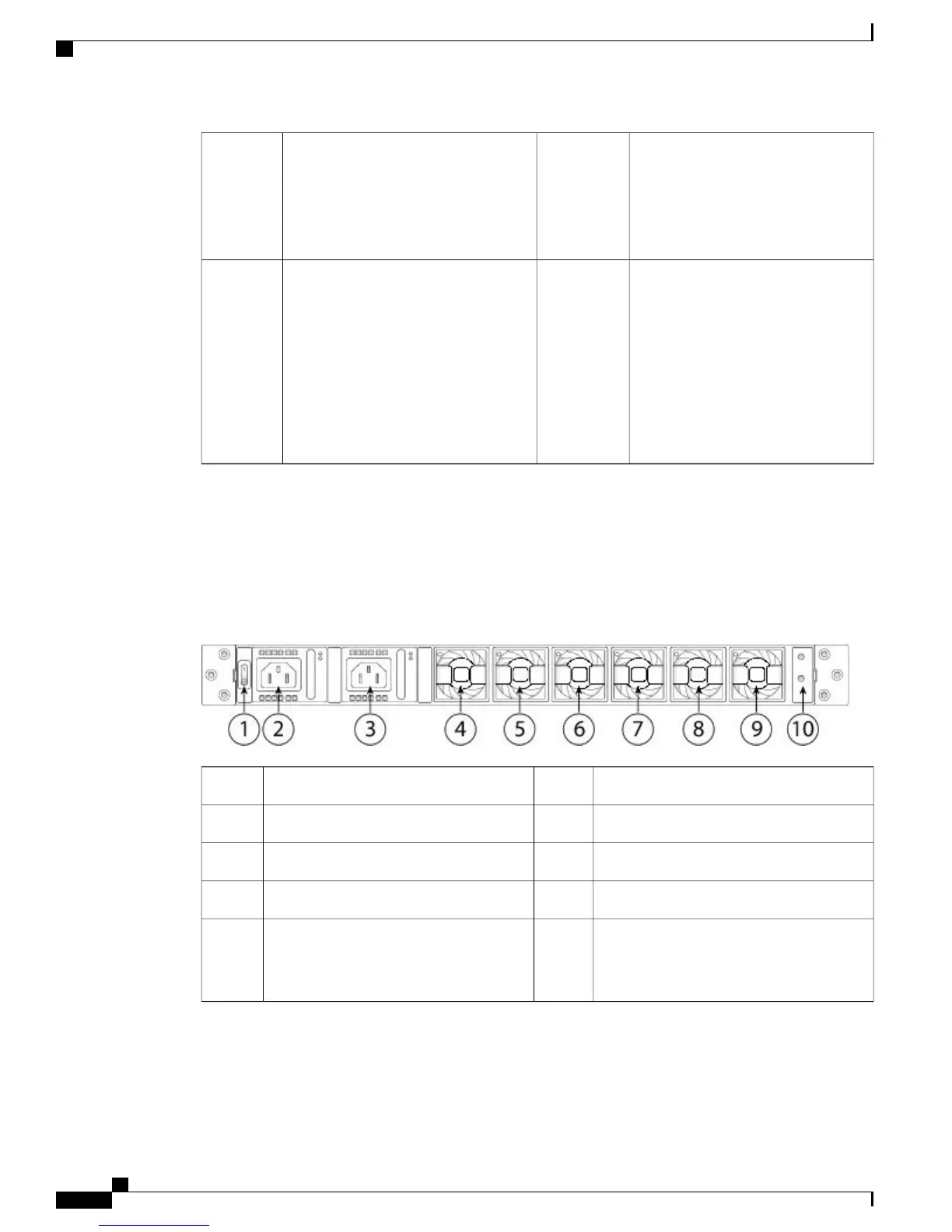
Rear Panel
The following figure shows the rear panel of the Firepower 4100 series security appliance.
Figure 6: Firepower 4100 Series Rear Panel
Power supply module 12Power on/off switch1
Fan module 14Power supply module 23
Fan module 36Fan module 25
Fan module 58Fan module 47
Location for the two-post grounding lug
The two-post grounding lug is
included in the accessory kit.
Note
10Fan module 69
Cisco Firepower 4100 Series Hardware Installation Guide
8
Overview
Rear Panel
 Loading...


