Do not switch the 2 SSDs. The MSP MUST be installed in slot 2. If you remove it and install it in slot 1,
all stored file capture data is lost.
Caution
Step 1
Save your configuration.
Step 2
Power down the chassis by moving the power switch to the OFF position. See About the Cisco Firepower 4100 Security
Appliance, on page 1 for more information about the power switch.
Step 3
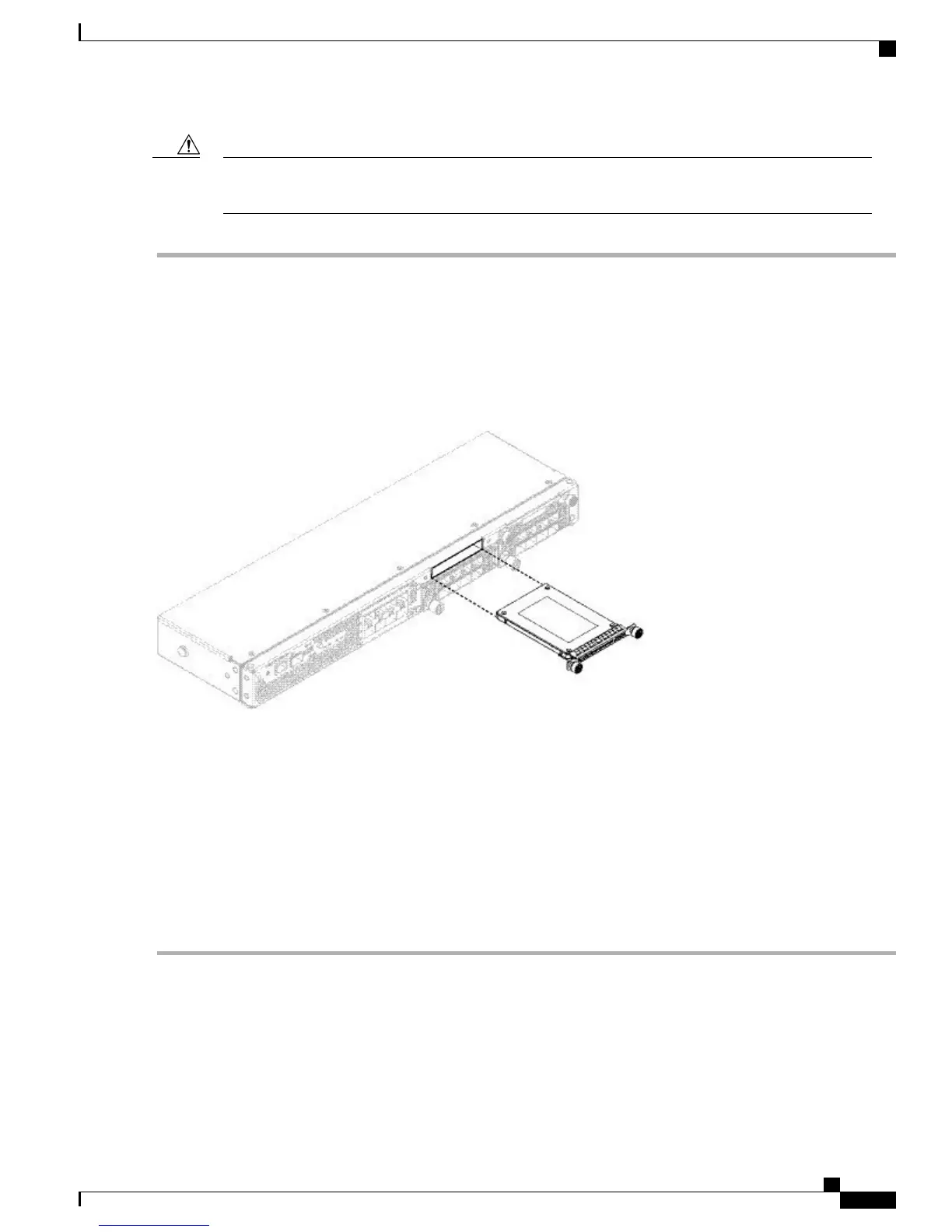
To remove an SSD, face the front of the chassis, loosen the 2 captive screws on the SSD, and gently pull it out of slot 1
of the chassis.
Figure 43: Remove the SSD
Step 4
To replace the SSD, make sure the power switch is still in the OFF position, and then hold the SSD in front of slot 1 and
push it in gently until it is seated.
Step 5
To install the MSP SSD, make sure the power switch is still in the OFF position and then remove the blank faceplate in
Slot 2 by loosening the captive screws on either side of the faceplate.
Step 6
Hold the MSP SSD in front of slot 2 and push it in gently until it is seated.
Do not switch the 2 SSDs. The MSP MUST be installed in slot 2. If you remove it and install it in slot 1, all
stored file capture data is lost.
Caution
Step 7
Tighten the captive screws on either side of the SSD.
Step 8
Verify that the SSD is operational by checking the SSD LED. See Front Panel LEDs, on page 7 for a description of
the fan LEDs.
Remove and Replace the Power Supply Module
Take note of the following warnings:
Cisco Firepower 4100 Series Hardware Installation Guide
65
Maintenance and Upgrades
Remove and Replace the Power Supply Module
 Loading...


