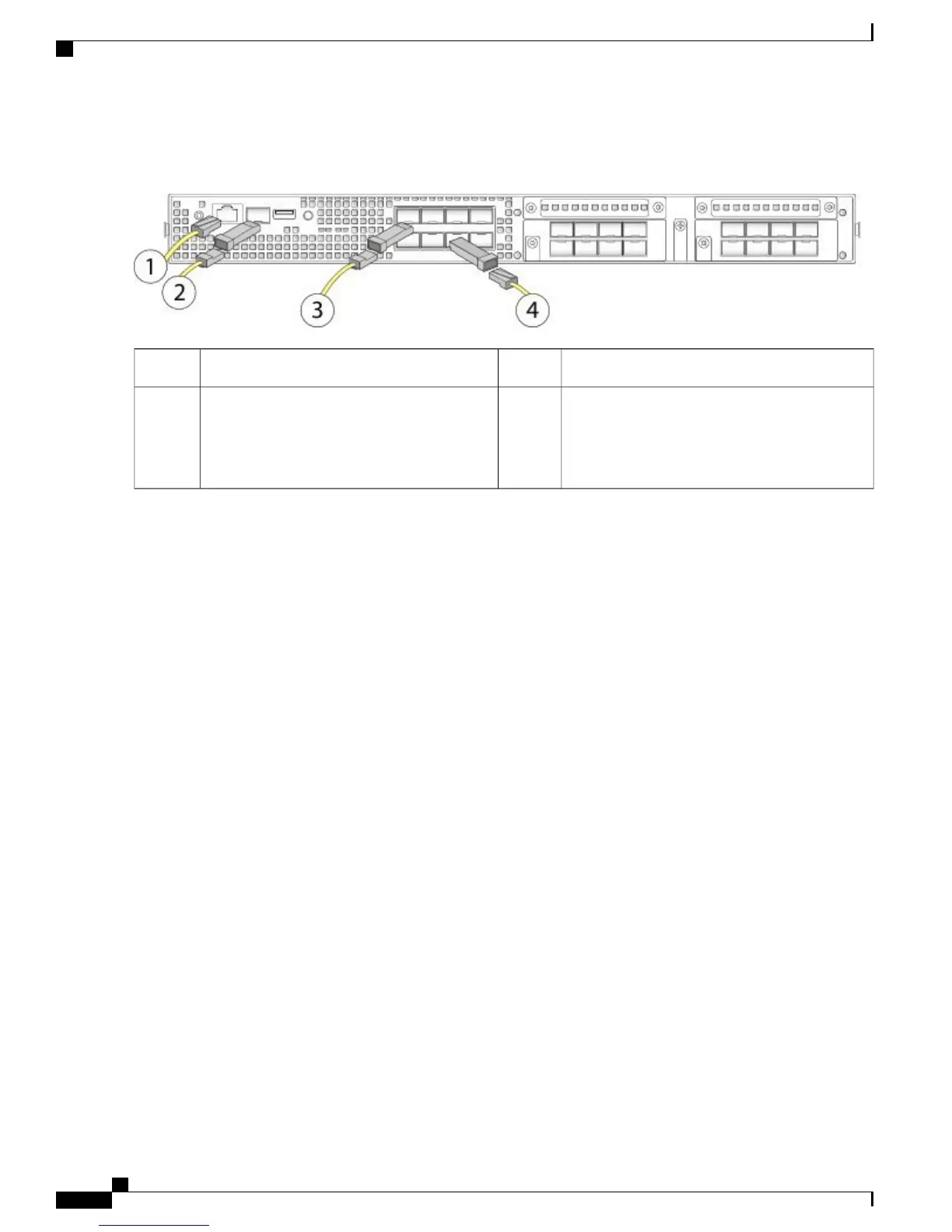
Figure 40: Connecting the Cables to the Firepower 4100 Security Appliance
1 Gigabit Ethernet Management interface (RJ-45)2Console port (RJ-45)1
8 fixed-port Gigabit Ethernet data interfaces for
SFP+ transceivers
48 fixed-port Gigabit Ethernet data interfaces
for SFP+ transceivers
Flip the SFP+ over to connect in the upper
ports.
3
Step 3
Install the SFP/SFP+ transceivers.
Install SFP/SFP+/ transceivers in the Ethernet network interfaces in the fixed ports or in the network modules you have
installed taking care not to touch the contacts in the rear.
Flip the SFP+ over to connect in the upper ports. The SFP+ connects in the normal way in the lower ports.
The sockets on the upper row face up and the sockets on the lower row face down.
Use appropriate electrostatic discharge (ESD) procedures when inserting the transceiver. Avoid touching the
contacts at the rear, and keep the contacts and ports free of dust and dirt. Store unused SPFs in their ESD
packaging.
Note
Do not force an SFP transceiver into a socket. This can jam the transceiver and can cause permanent damage
to the transceiver, the chassis, or both.
Warning
Although non-Cisco SFPs are allowed, we do not recommend using them because they have not been tested
and validated by Cisco. Cisco TAC may refuse support for any interoperability problems that result from
using an untested third-party SFP transceiver. See Supported SFP/SFP+ Transceivers, on page 21 for a list
of supported Cisco transceivers.
Caution
Step 4
Connect the Ethernet interfaces.
Use the proper cable to connect the SFP/SFP+ transceivers in the fixed ports or in the network modules you have installed.
Step 5
(Optional) If you are installing the FIPS opacity shield, continue with step 6 in Install the FIPS Opacity Shield, on page
50.
Step 6
Attach the power cable to the appliance and connect it to an electrical outlet.
Step 7
Press the power switch on the rear panel.
Step 8
Check the power LED on the front panel. Solid green indicates that the appliance is powered on.
When you toggle the power switch from ON to OFF, it takes several seconds for the system to power off. During
this time, the power LED on the front panel blinks green. Do not remove the power cable until the power LED
is completely off.
Note
Step 9
See the quick start guide for your operating software for further configuration information:
•
Cisco ASA for Firepower 4100 Quick Start Guide
Cisco Firepower 4100 Series Hardware Installation Guide
56
Mount and Connect
Connect Cables, Turn on Power, and Verify Connectivity
 Loading...


