15
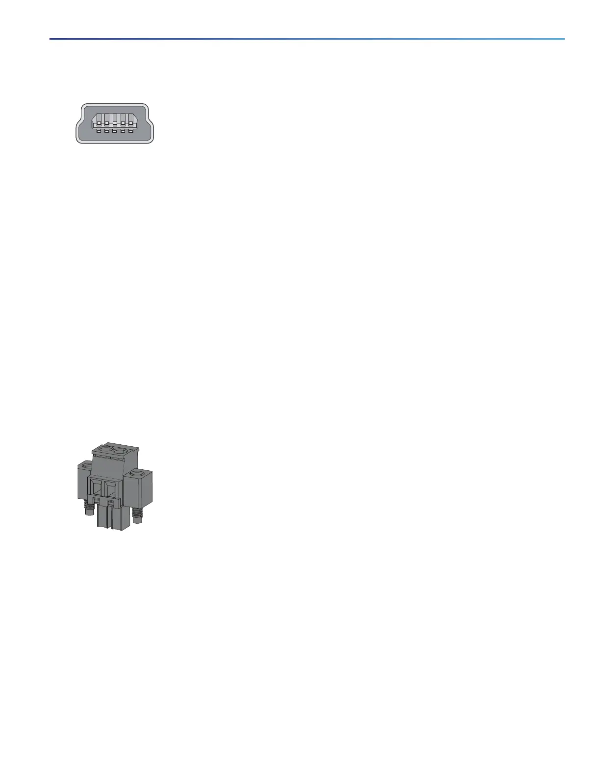
Figure 5 USB Mini-Type B Port
The configurable inactivity timeout reactivates the RJ-45 console port if the USB-mini console port is activated, but no
input activity occurs for a specified time period. When the USB-mini console port deactivates due to a timeout, you can
restore its operation by disconnecting and reconnecting the USB cable. For information on using the CLI to configure the
USB-mini console interface, see the switch software guide.
Power Connectors
DC Power Connector, page 15
PoE Power Connector, page 15
DC Power Connector
You connect the DC power to the switch through the front panel connectors. The switch has a dual-feed DC power
supply; two connectors provide primary and secondary DC power (DC-A and DC-B). The DC power connectors are near
the top right of the front panel (see Figure 2 on page 10). Each power connector has an LED status indicator.
The switch power connectors are attached to the switch chassis. Each power connector has screw terminals for
terminating the DC power (see Figure 6 on page 15). All connectors are attached to the switch front panel with the
provided captive screws.
The power connector labeling is on the panel. The positive DC power connection is labeled “+”, and the return
connection is labeled “–”.
Figure 6 Power Connector
The switch can operate with a single power source or with dual power sources. When both power sources are
operational, the switch draws power from the DC source with the higher voltage. If one of the two power sources fail,
the other continues to power the switch.
PoE Power Connector
The IE 2000 switch models with PoE capability (IE-2000-16PTC-G-E, IE-2000-16PTC-G-L, and IE-2000-16PTC-G-NX)
are equipped with an additional DC input terminal block. This DC terminal block allows the connection of a second power
supply (see the Power over Ethernet Ports, page 14), or a second input from site source DC power to operate the PoE
ports. The PoE terminal block accepts 48 VDC or 54 VDC at 2.5 A.
 Loading...


