9
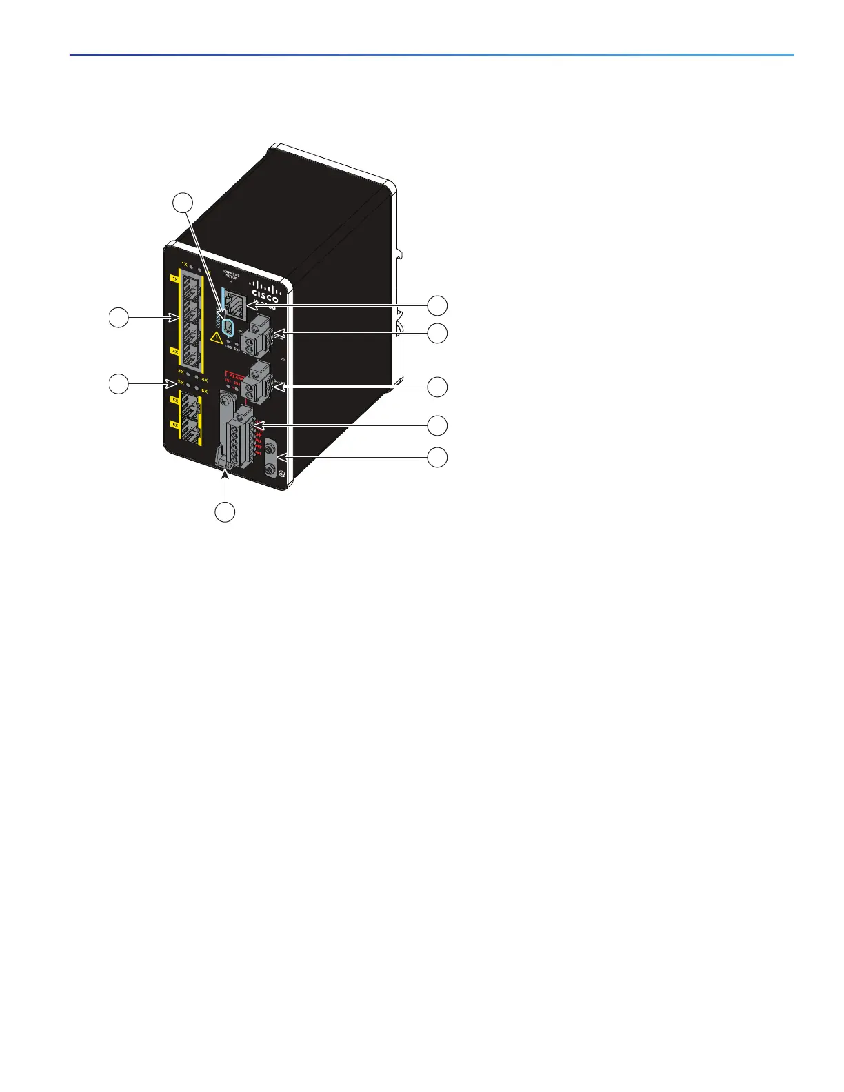
Figure 1 Cisco IE-2000-4S-TS-G-B Front Panel View
1 SFP module slots (downlink ports) 6 Power connector DC-B
2
2 SFP module slots (uplink ports) 7 Alarm connector
3 USB mini-Type B (console) port
1
8 Protective ground connection
4 RJ-45 console port 9 Flash memory card slot
1
5 Power connector DC-A
2
1
Use a screwdriver to remove the port cover and access the port.
2
Remove the plastic cover to access the power connector.
4S-TS
±1
2
/2
4
/4
8
0
.5
-2.
0
A
1
3
2
4
5
6
7
8
380287
9
 Loading...


