1-2
Cisco IR829 Integrated Services Router Hardware Installation Guide
Chapter 1 Product Overview
General Description
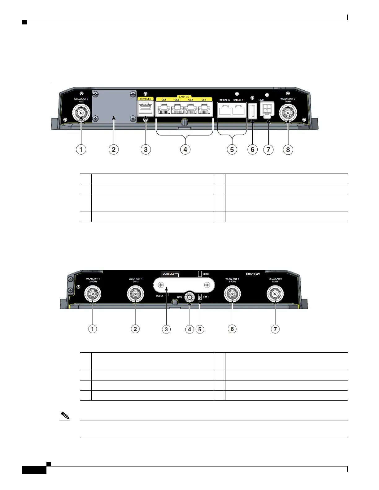
Figure 1-2 shows the front panel details of the Cisco IR829.
Figure 1-2 Cisco IR829 Front Panel
Figure 1-3 shows the back panels details of the Cisco IR829.
Figure 1-3 Cisco IR829 Back Panel
Note Behind the SIM Door Assembly, there is a reset switch, Mini USB Debug connection, and Dual SIM
slots. See Figure 1-4 for details
1 CELLULAR 0 AUX 5 Serial Ports
2 Limited Modularity Slot 6 USB-A Port
3 Gigabit WAN 7 Power Input, Battery, and Ignition connector.
Refer to the DC Power section for pin-outs.
4 Gigabit LAN/PoE 8 WLAN ANT0 5GHz
1 WLAN ANT 0 2.4GHz 5 SIM connection 1 (SIM connection 0 is
above)
2 WLAN ANT 1 5GHz 6 WLAN ANT 1 2.4GHz
3 SIM Door Assembly 7 CELLULAR 0 MAIN
4 GPS SMA
 Loading...