Management port link status LEDs
(2)
11slot0 USB3 port4
Fan status LED12RS232 serial console port (fixed RJ45
connector)
5
Power status LED13mgmt0 Ethernet out of band
management port
(10/100/1000Base-T, fixed RJ45
connector)
6
System status LED14mgmt1 Ethernet out of band analytics
port
Note: The MGMT1 ETH port is not
yet supported.
7
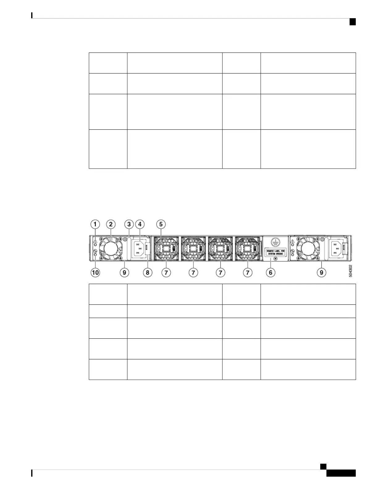
Rear View
The following figure shows the rear view of the switch:
Figure 2: Rear View of the Switch
Ground pad6Power supply failure status LED (1
per PSU)
1
Chassis fan modules (4)7Power supply unit fan (1 per PSU)2
Power supply unit latch release (1 per
PSU)
8Power supply unit handle (1 per PSU)3
Power supply units (2)9Unswitched power socket (IEC C14,
1 per PSU)
4
Power supply status LED (1 per PSU)10Chassis fan module release latches (2
per fan module)
5
Cisco MDS 9148V-K9 Switch Hardware Installation Guide
7
Overview of Cisco MDS 9148V-K9 Switch
Rear View
 Loading...