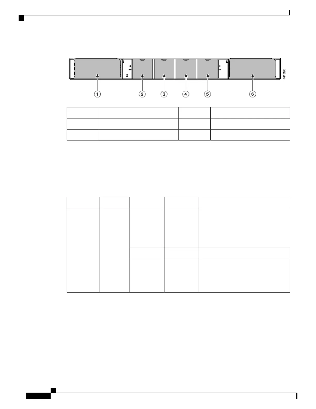
Figure 3: Rear Panel Slot Numbering of Cisco MDS 9148T
Chassis fan module slot 34Power supply unit slot 11
Chassis fan module slot 45Chassis fan module slot 12
Power supply unit slot 26Chassis fan module slot 23
LEDs
The switch has LEDs on both the front and back of the switch to indicate the status of different system
components during bootup tests and online operation. The following tables describe the location of each LED
and the meaning of its color:
Table 1: Chassis Activity LEDs for the Switch
StateStatusColorFunctionIndicator
Either of the following conditions exists:
• The system is not receiving sufficient
power from the PSUs.
• The operating system is not running.
OffOffChassis
Power/Health
PWR: Power
LED
(front panel of
the chassis)
Both PSUs are installed and operational.Solid OnGreen
Either of the following conditions exists:
• A PSU has failed.
• A PSU has been removed.
Solid OnRed
Cisco MDS 9148V-K9 Switch Hardware Installation Guide
8
Overview of Cisco MDS 9148V-K9 Switch
LEDs
 Loading...