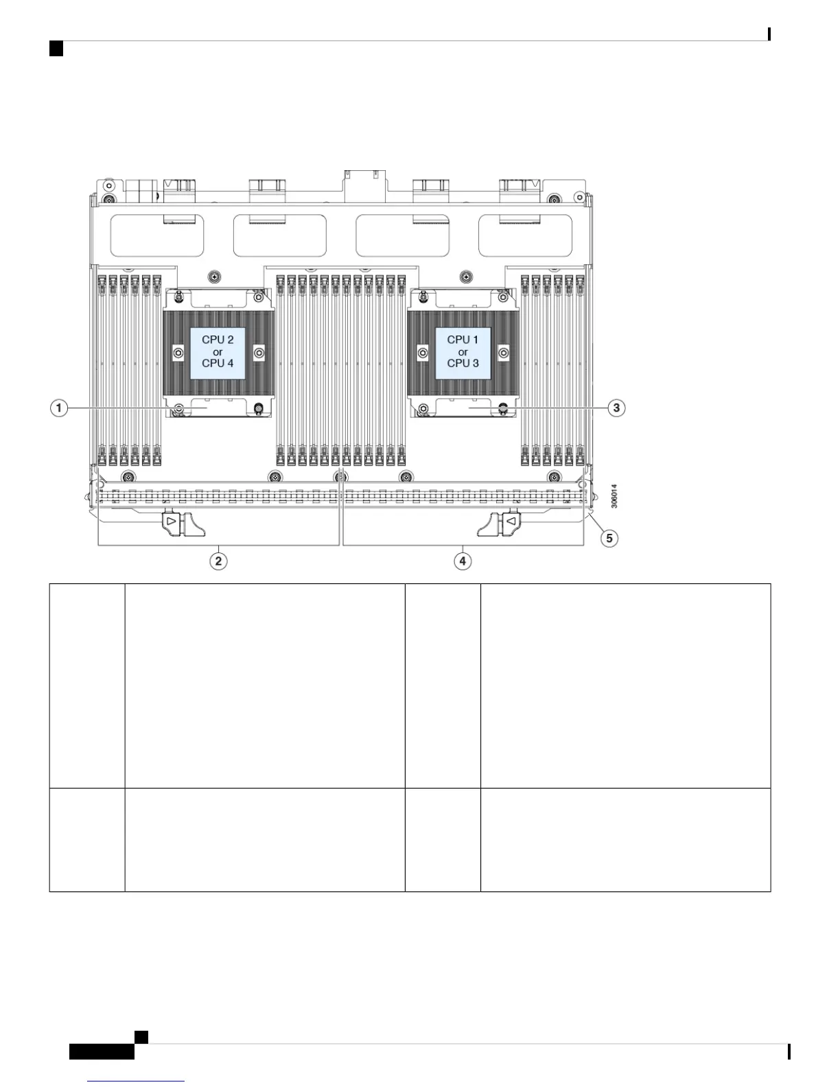
Serviceable Components Inside a CPU Module
Figure 4: Serviceable Component Locations Inside a CPU Module
DIMM sockets controlled by CPU 1 or 3 (channels
A, B, C, D, E, F.)
4CPU number differs depending on the CPU module
location:
• CPU 2 and heatsink (when module is in lower
bay 1)
• CPU 4 and heatsink (when module is in upper
bay 2)
The CPUs in CPU module 1 must be
identical with the CPUs in CPU module
2 (no mixing).
Note
1
Release levers for module (two each module)5DIMM sockets controlled by CPU 2 or 4 (channels
G, H, J, K, L, M.)
See DIMM Population Rules and Memory
Performance Guidelines, on page 108 for DIMM
slot numbering.
2
Cisco UCS C480 M5 Server Installation and Service Guide
8
Overview
Serviceable Component Locations
 Loading...