-CPU number differs depending on the CPU module
location:
• CPU 1 and heatsink (when module is in lower
bay 1)
• CPU 3 and heatsink (when module is in upper
bay 2)
The CPUs in CPU module 1 must be
identical with the CPUs in CPU module
2 (no mixing).
Note
3
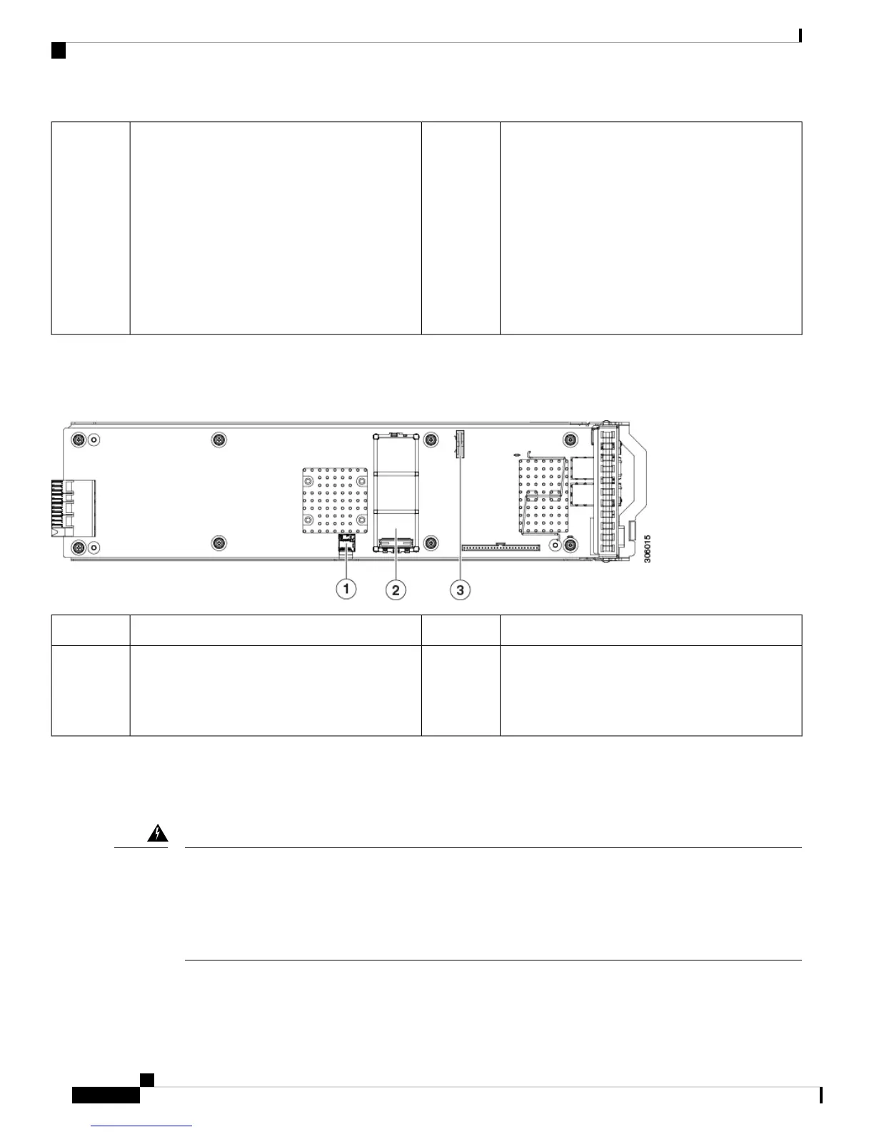
Serviceable Components Inside an I/O Module
Figure 17: Serviceable Component Locations Inside an I/O Module
RTC battery vertical socket3Micro SD card socket1
-Mini storage module connector
Supports either an SD card carrier with two SD
card slots or an M.2 SSD carrier with two SATA
M.2 SSD slots.
2
Replacing Components Inside the Main Chassis
Blank faceplates and cover panels serve three important functions: they prevent exposure to hazardous
voltages and currents inside the chassis; they contain electromagnetic interference (EMI) that might
disrupt other equipment; and they direct the flow of cooling air through the chassis. Do not operate the
system unless all cards, faceplates, front covers, and rear covers are in place.
Statement 1029
Warning
Cisco UCS C480 M5 Server Installation and Service Guide
44
Maintaining the Server
Replacing Components Inside the Main Chassis
 Loading...