Replacing Components Inside a CPU Module
When handling server components, handle them only by carrier edges and use an electrostatic discharge (ESD)
wrist-strap or other grounding device to avoid damage.
Caution
This section describes how to install and replace CPUs and DIMMs inside a CPU module.
Never remove a CPU module without shutting down and removing power from the server.
Caution
See also:
• Replacing Components Inside the Main Chassis, on page 44
• Replacing Components Inside an I/O Module, on page 111
Replacing CPUs and Heatsinks
This section contains information for replacing CPUs and heatsinks inside a CPU module.
CPU Configuration Rules
The CPUs in this server install to sockets inside one or two removable CPU modules. Each CPU module has
two CPU sockets.
• The system numbers the CPUs in CPU module 1 (the lower bay) as CPU 1 and CPU 2.
• The system numbers the CPUs in CPU module 2 (the upper bay) as CPU 3 and CPU 4.
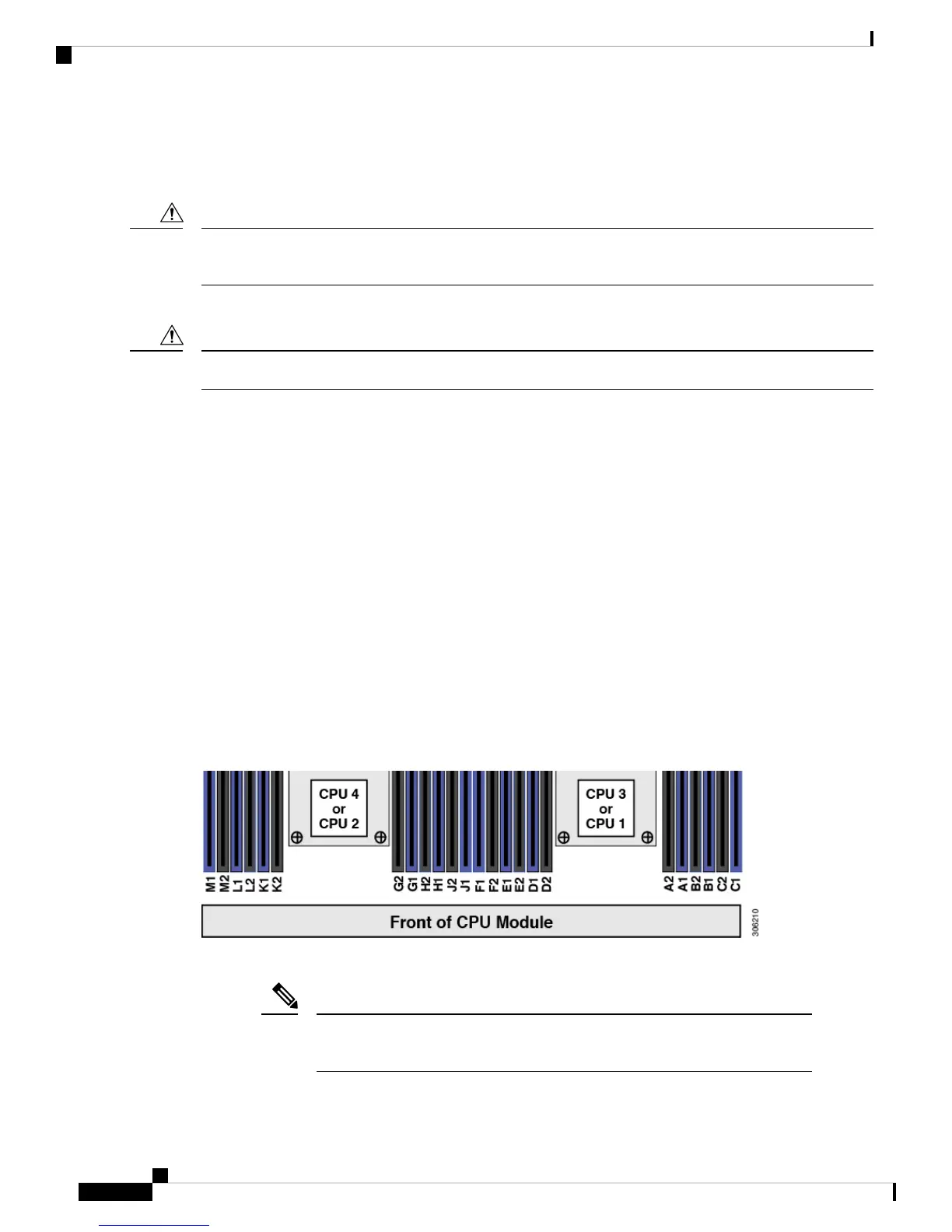
Figure 43: CPU Numbering
• The server can operate with one or two CPU modules (two or four identical CPUs) installed.
The CPUs in CPU module 1 must be identical with the CPUs in CPU module 2
(no mixing).
Note
Cisco UCS C480 M5 Server Installation and Service Guide
94
Maintaining the Server
Replacing Components Inside a CPU Module
 Loading...