5-24
Cisco 2900 Series and 3900 Series Hardware Installation Guide
OL-18712-03
Chapter 5 Installing and Upgrading Internal Modules and FRUs
Installing and Removing PVDM2s
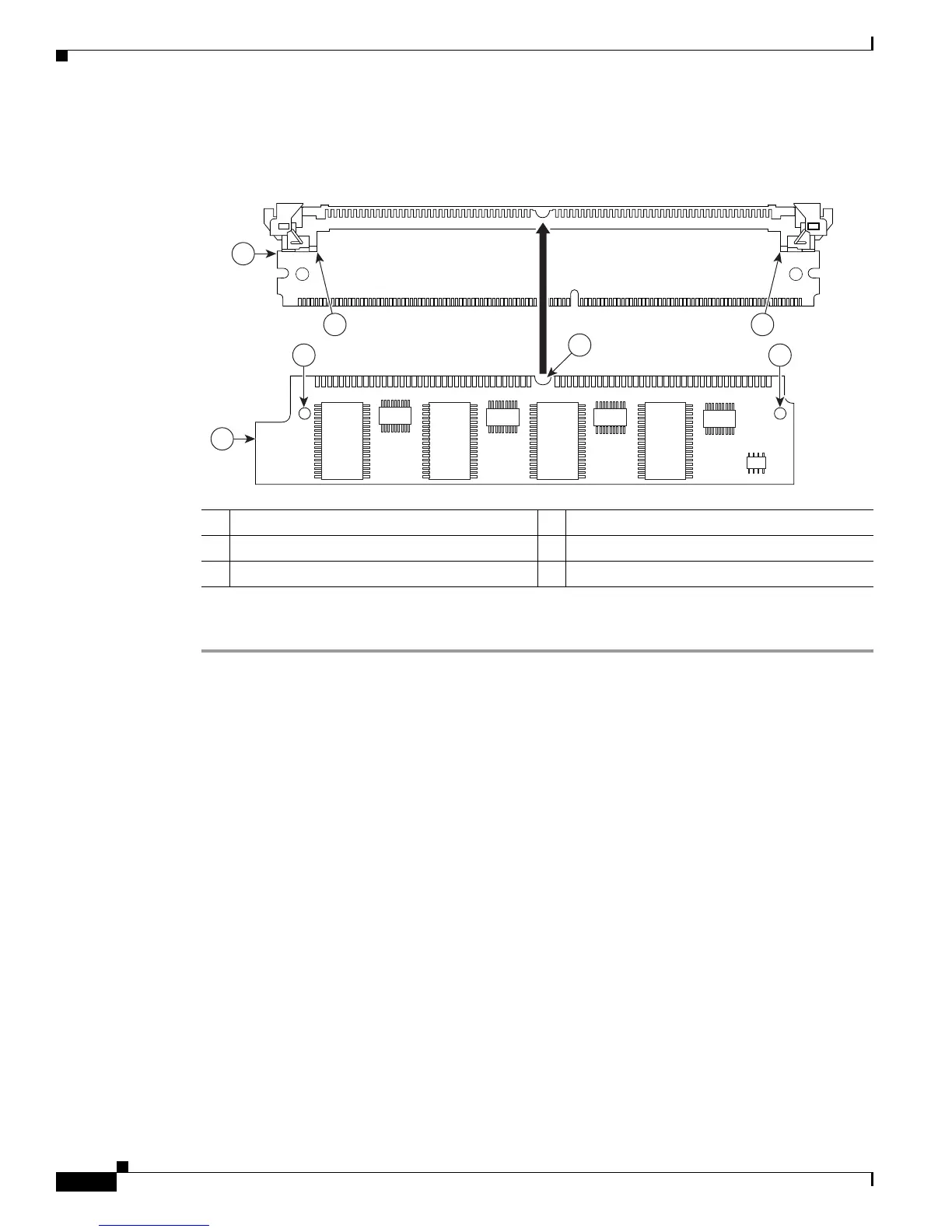
Figure 5-18 PVDM Adapter Components
To install a PVDM2 into the PVDM3 slot, perform the following steps:
Step 1
Read the “Safety Warnings” section on page 5-2 section and disconnect the power supply before you
perform any module replacement.
Step 2
Ensure that both retainer clips are open (the UP position). (See Figure 5-19, Figure 5-20, and
Figure 5-21.)
Figure 5-19 shows the retainer clip, connector clip, and guide post locations on the adapter.
1 PVDM adapter 2 PVDM2
3 Orientation notch 4 Guide post holes
5 Guide posts
 Loading...