5-18
Cisco 2900 Series and 3900 Series Hardware Installation Guide
OL-18712-03
Chapter 5 Installing and Upgrading Internal Modules and FRUs
Installing and Removing ISMs
Step 7
Replace the chassis cover. For Cisco 2900 series, see the “Removing and Replacing the Chassis Cover”
section on page 5-4. For Cisco 3900 series, see the “Removing and Replacing the Services Performance
Engine” section on page 5-6.
Installing an ISM
To install an ISM, use a number 2 Phillips screwdriver or flat-blade screw drive, and a 1/4-inch nut driver
or wrench. Cisco 2900 and Cisco 3900 series routers have one ISM connector on the system board.
Step 1
Read the “Safety Warnings” section on page 5-2 and disconnect the power supply before you perform
any module replacement.
Step 2
Access the ISM slot. For Cisco 2900 series, see the “Removing and Replacing the Chassis Cover”
section on page 5-4. For Cisco 3900 series, see the “Removing and Replacing the Services Performance
Engine” section on page 5-6.
Step 3
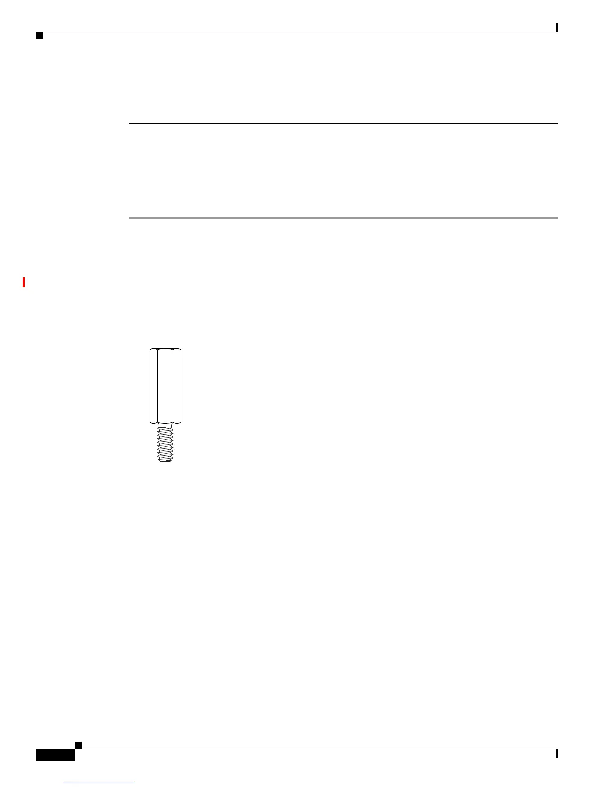
Locate the four standoffs from the accessory kit. See Figure 5-13.
Figure 5-13 Standoffs
Step 4
Install the four standoffs into the system board in the attachment locations, as shown in Figure 5-14. Use
a 1/4-inch nut driver to tighten the standoffs. The locations for ISM standoffs have white plastic
grommets surrounding the mounting hole location.
 Loading...