D
GB
9 Direktzapfung Direct connection
8 Installation
(Fortsetzung)
Installation
(continuation)
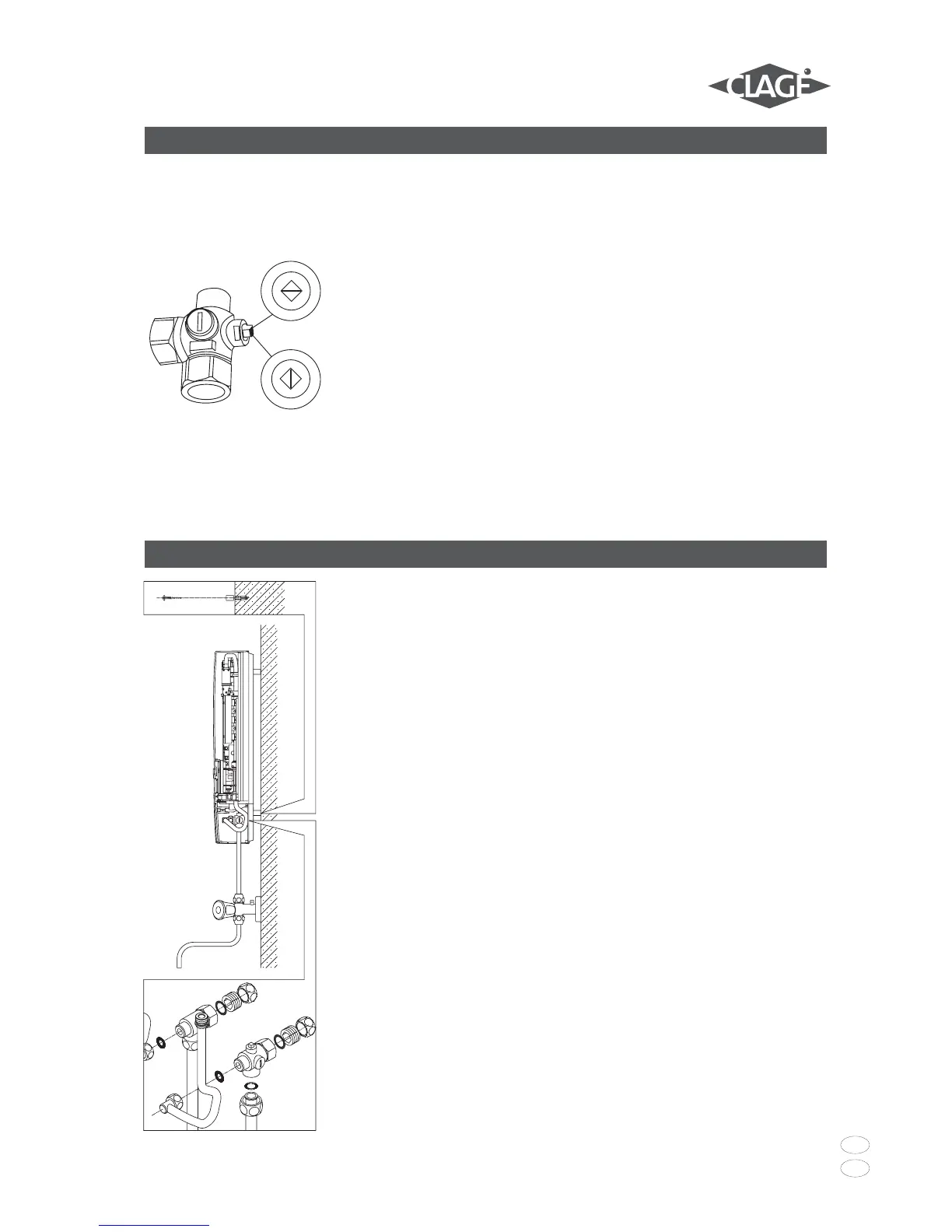
3. Schrauben Sie die beiden 3/8“-
Überwurfmuttern der Wasser-
anschlussleitungen des Gerätes
jeweils mit der 3/8“-Dichtung auf die
installierten Anschlussstücke.
4. Schrauben Sie die Kunststoffrändel-
mutter auf die Gewindestange des
Wandhalters.
5. Öffnen Sie die Wasserzuleitung und
drehen Sie das Absperrventil (20c) im
Kaltwasseranschlussstück (20)
langsam auf (Pos. I). Prüfen Sie alle
Verbindungen auf Dichtigkeit.
6. Öffnen und schließen Sie danach
mehrfach das zugehörige Warm-
wasserzapfventil bis keine Luft mehr
aus der Leitung austritt und der
Durchlauferhitzer luftfrei ist.
3.Screw the two 3/8" union nuts of the
appliance's water connection pipes,
each with the 3/8" seal, onto the
fittings.
4.Screw the plastic knurled nut onto the
threaded rod of the wall bracket.
5.Open the water supply line to the unit
and slowly open (Pos.I) the shut-off
valve (20c) in the cold water
connection piece (20). Check all
connections for leaks.
6.Next, open and close the hot water
tapping valve several times until no
more air emerges from the line and all
air has been eliminated from the
instantaneous water heater.
Bei Direktzapfung sind die beiden 1/2“
Einschraubnippel (23) und die 1/2“ Dich-
tungen mit den 1/2“ Überwurfmuttern
des Warmwasser- (1) und Kaltwasser-
anschlussstückes (20) zu verschrauben.
Die beiden 1/2“ Blindkappen der
seitlichen Abgänge des Warm- (1) und
Kaltwasseranschlussstückes (20) sind zu
demontieren und mit dem offenen Ende
der Einschraubnippel (23) zu
verschrauben. Die Warm- und Kalt-
wasseranschlussstücke sind dann mit
den 3/8“ Dichtungen an die 3/8“
Überwurfmutter des Gerätes und
Auslaufrohres zu verschrauben.
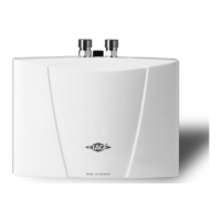
Bei Direktzapfung ist es sinnvoll, das
Gerät mittels der mitgelieferten
Distanzhülsen gemäß nebenstehender
Zeichnung auf Abstand zu montieren.
Dabei ist zu beachten, dass auch die
beiden Befestigungsbohrungen im
unteren Rohranschlussbereich benutzt
werden.
Die Bördelseite der Rohre sind mit 1/2“
Überwurfmuttern und 1/2“ Dichtungen
an die seitlichen 1/2“ Abgänge des
Warm- (1) und Kaltwasseranschluss-
stückes (20) zu schrauben. Abschließend
sind die Ausbrüche für die Rohre in der
Haube mit einem stumpfen Gegenstand
herauszubrechen.
For direct connection, the two 1/2"
screw-in nipples (23) and the 1/2" seals
must be screwed into the 1/2" union
nuts of the hot-water (1) and cold-water
(20) connectors. The two 1/2" caps of
the side outlets of the hot-water (1) and
cold-water (20) connectors must be
removed and screwed onto the open end
of the screw-in nipples (23). The hot-
water and cold-water connectors must
then be screwed into the 3/8" union nut
of the appliance and delivery pipe,
together with the 3/8" seals.
For direct connection, it is advisable to
mount the appliance at a distance as
illustrated alongside, using the spacer
sleeves supplied. It should therefore be
noted that the two fixing holes near the
lower pipe connections are also used.
The flared end of the pipes must be
screwed into the 1/2" side outlets of the
hot-water (1) and cold-water connectors
with 1/2" union nuts and 1/2" seals. The
holes required for the pipes must then
be broken out of the housing with the
aid of a blunt implement.
9
20c
II
I
 Loading...