9. INSTALLATION
I
WIRE
CONNECTION GUIDE
CONTENTS
1 ) Before Starting ...................................................................... 16
2) Package Contents ................................................................. 16
3)
General
Preautions ............................................................... 16
4)
Cautions
on
Installation
......................................................... 16
5)
Installing
the Source Unit ...................................................... 16
6) Cautions
on
Wiring ............................................................... 17
7)
Sample
Systems .................................................................. 17
8) Wiring and Connections .......
..
.........................
..
.................... 18/19
9)
Connecting the accessories .................................................. 18/19
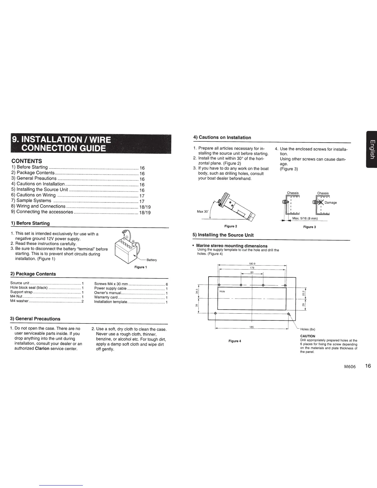
1) Before Starting
1.
This set is intended
exclusively
for use with a
negative ground 12V power supply.
2.
Read these instructions
carefully.
3.
Be sure to disconnect the battery
"terminal" before
starting. This
is
to prevent short circuits during
installation.
(Figure
1)
Battery
2) Package Contents
Source
unit ...................................
..
.............
1
Hole
block
seal (black)
..............................
..
1
Support
strap
..
..............................
..
.............
1
M4
Nut
..........
..
.............................................
1
M4
washer
...................
..
.............................. 2
3)
General
Precautions
1. Do not open the case. There are no
user
serviceable
parts inside.
If
you
drop anything into the unit during
installation, consult
your dealer
or an
authorized
Clarion
service center.
Figure 1
Screws
M4
x
30
mm
....................................
6
Power
supply
cable
......................
..
...........
..
1
Owner's
manual.
..........................................
1
Warranty
card ..............................................
1
Installation
template
.............. ......
..
.....
..
........ 1
2.
Use a soft, dry
cloth
to
clean
the case.
Never use a rough
cloth,
thinner,
benzine, or
alcohol
etc. For tough dirt,
apply
a damp soft cloth
and wipe dirt
off
gently.
4) Cautions on
Installation
1.
Prepare
all articles
necessary for in-
stalling
the source unit before starting.
4.
Use the
enclosed
screws for
installa-
tion.
2.
Install
the unit within
30° of the hori-
zontal plane.
(Figure
2)
3.
If
you have to do any work on the boat
body, such as
drilling holes, consult
your boat
dealer
beforehand.
Figure 2
5) Installing
the Source Unit
•
Marine stereo mounting dimensions
Using the
supply template
to cut the hole
and
drill
the
holes. (Figure
4)
180
9
179
60
Hole
-
-
185
Figure 4
Using other screws can cause dam-
age.
(Figure
3)
---4
Chassis Chassis
t~a~age
Max.
5/16
(8
mm)
r\
Figure 3
N
C\i
N
--
a>
N
Holes
(6x)
CAUTION
Drill appropriately
prepared
holes
at
the
6
places
for
fixing
the
screw depending
on
the
materials
and
plate
thickness
of
the
panel.
M606
16

 Loading...