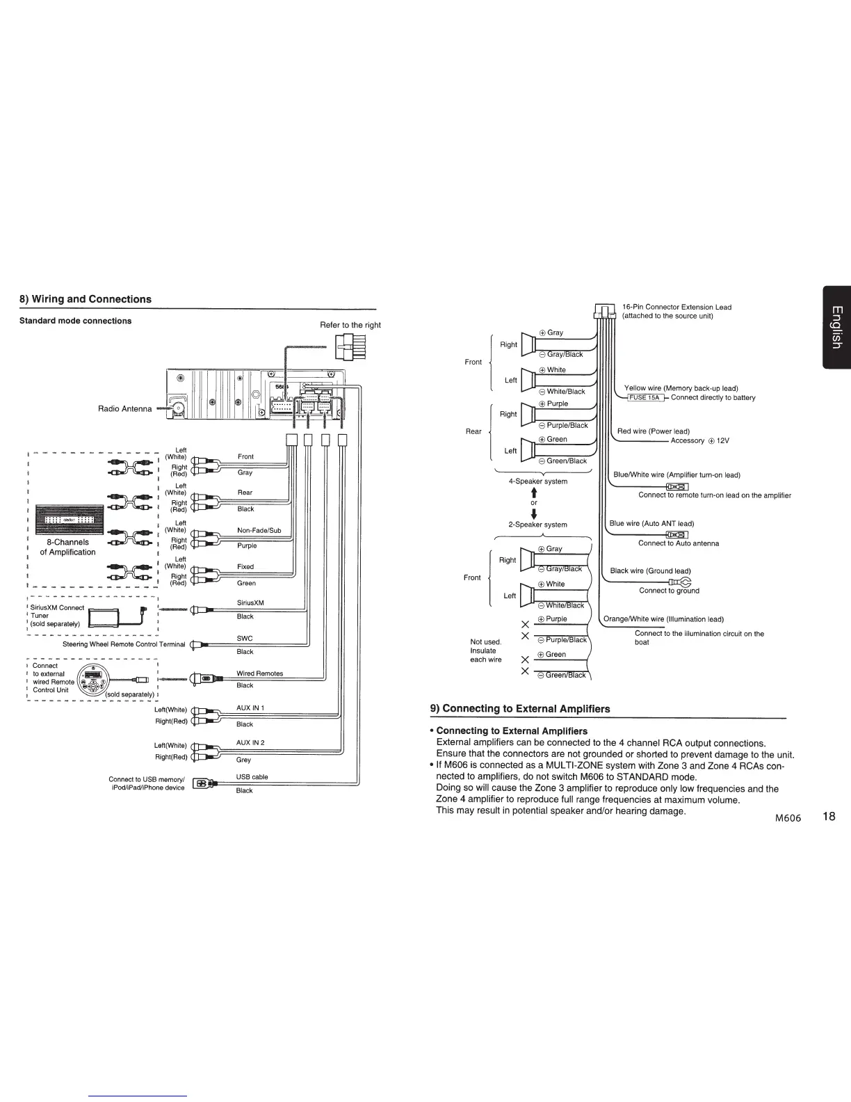
8) Wiring and Connections
Standard mode connections
=---~
-_
-
==---~
~1iilliDmli~
-
-=-==-~--
-
~~
~
a-Channels
1
of
Amplification
I
~
·
I
~
~
,
__
____
_
____
_ _ .,.!
~----------------
-~
I
SiriusXM Connect
r
'-
1Tuner
D .
1
:
(sold
separately)
Front
Gray
Green
SiriusXM
Black
swc
Steering
Wheel
Remote
Control Terminal
(C)II:==================~
Black
~------
--------
---
1
Connect
I
Connect
to
USB
memory/
iPodliPad/iPhone device
Wired Remotes
Black
USB cable
~~==================~
Black
Front
Rear
l
Right
Left
l
Right
Left
lack
~White
8 White/Black
~Purple
8
Purple/Black
~Green
8
Green/Black
4-Speaker system
16-Pin Connector Extension Lead
(attached to the source unit)
Yellow wire (Memory back-up
lead)
FUSE 15A
Connect
directly to battery
Red wire (Power
lead)
------Accessory
~
12V
Blue/White wire (Amplifier
turn-on
lead)
t
Connect to remote turn-on
lead
on the
amplifier
or
•
2-Speaker system
l
Right
Front
Left
X
Not used.
X
Insulate
each wire
X
X
Blue
wire (Auto ANT lead)
Connect to Auto antenna
Black wire (Ground
lead)
Connect to ground
Orange/White wire
(Illumination lead)
Connect to the illumination circuit on the
boat
9) Connecting
to
External Amplifiers
•
Connecting
to
External Amplifiers
External amplifiers
can be connected to the 4
channel
RCA output connections.
Ensure that the connectors are not grounded or shorted to prevent damage to the unit.
• If M606
is connected as a
MULTI-ZONE
system with Zone
3
and Zone
4
RCAs
con-
nected to
amplifiers,
do not switch
M606
to STANDARD mode.
Doing so
will cause the Zone
3
amplifier
to reproduce only low frequencies and the
Zone 4
amplifier
to reproduce
full range frequencies at maximum volume.
This may
result in
potential
speaker and/or hearing damage.
M606
18
 Loading...