EasyManua.ls Logo

Clevo W670SZQ User Manual

Clevo W670SZQ
106 pages
To Next Page IconTo Next Page
To Previous Page IconTo Previous Page
Page #92 background imageLoading...
Page #92 background image
Schematic Diagrams
B - 36 AUDIO CODEC VT1802S
B.Schematic Diagrams
AUDIO CODEC VT1802S
C482
100p_50V_NPO_04
PCBEE P
2
J_SPK1
1
C464
*1u_6. 3V_X5R_04
C465
*1u_6. 3V_X5R_04
3. 3VS3,6,9,10,11,12,19,20,21,22,23,24,26,27,28,29,30,31,32,33,34,36,37,41
5VS12,19, 20,30,33, 34,35,37, 41,42
C466 10u_6.3V_X5R_06
Close to PCH
Layout Note:
C665
100p_50V_NPO_04
R539 1K_04
C458
0.1u_16V_Y5V_04
HP_SENSE 33
MIC _S EN SE 3 3
BEEP36
HD A_SPKR20
L41
*HCB1005KF-121T20
C487 100p_50V_NPO_04
C441 10u_6.3V_X5R_06
R288 5.1K_1%_04
INT_MIC_OUT
DIGITAL
ANALOG
U18
VT1802S
DVDD1
1
GPIO0-DMIC-DAT
2
GPIO1-DMIC-CLK
3
PD#
4
SDATA-OUT
5
BIT-CLK
6
DVSS2
7
SDATA-IN
8
DVDD-IO
9
SYNC
10
RESET#
11
PCBEEP
12
Sense A
13
LINE2-L
14
LINE2-R
15
MI C 2- L
16
MI C 2- R
17
Sense-B
18
JDREF
19
MON O-O UT
20
MI C 1- L
21
MI C 1- R
22
LINE1-L
23
LINE1-R
24
AVSS1
26
VREF
27
LDO_CAP
28
MIC2-VREFO
29
MIC 1- VR EF O-R
30
MIC1-VREFO-L
31
HP-OUT-L
32
AVSS2
37
OPVE E
34
CBN
35
CBP
36
HP-OUT-R
33
PVDD1
39
SPK-L+
40
SPK-L-
41
PVSS1
42
PVSS2
43
SPK-R+
45
SPK-R-
44
PVDD2
46
SPDIF C2/EAPD
47
SPDIF O
48
AVDD2
38
AVDD1
25
GND
49
C469
*180p_50V_NPO_04
INT_MIC
MIC2-VREFO
MI C 2_ R
MI C 2_ L
HDA_RST#R
C472 10u_6.3V_X5R_06
AZ_SDOUT_R
R291
*15mil_short_06
AZ_SY NC_ R
AZ_SDIN0_R
BEEP_R
LDO_CAP
SPKOUTL-
MIC1-VREFO-R
SPKOUTL+
MIC2-VREFO
OPVEE-ALC269
CBN-AL269
CBP-ALC269
MIC 1-R_R
MIC 1-L_R
C456
*10u_6.3V_X5R_06
SPKOUTL+_L
SPKOUTR+
SPKOUTR-
SPKOU TL+
SPKOUTL-_ L
C668
10u_6.3V_X5R_06
SPKOU TL-
SPKOUTR -_R
SPKOUTR +
MI C 1_ L
SPKOUTR -
SPKOUTR +_R
R540
3.3K_1%_04
MI C 1_ R
R310 4.7K_04
C442 10u_6.3V_X5R_06
C641 22p_50V_NPO_04
C438
*1u_6.3V_Y5V_04
R290 20K_1%_04
MIC 1_L
MIC 1_R
R275 75_04
MIC1-VREFO-R
MIC1-VREFO-L
R268 75_04
L44 HCB1005KF-121T20
C470
*180p_50V_NPO_04
R309 47K_04
C672
0.1u_16V_Y 5V_04
C462
180p_50V_NPO_04
C457 10u_6.3V_X5R_06
C483 1u_6.3V_X5R_04
R289 39.2K_1%_04
INT_MIC
C447 0.1u_16V_Y5V_04
C468
180p_50V_NPO_04
BEEP_L
C681
0.1u_16V_Y5V_04
C683
10u_6.3V_X5R_06
MI C 1- VR EF O -L
NEAR CODEC
KBC_MUTE#36
Speaker 4 ohm------> 40mils
Speaker 8 ohm------> 20mils
EMI Require
EMI Require
Layout note:
Close to codec
ANALOG
HDA_SDIN020
DIGITAL
C476
0.1u_16V_Y5V_04
C475
10u_6.3V_X5R_06
AZ_RST#
Thermal Pad place 9
Via hole.
GND and AUDG space is
60mils ~ 100mils
Speaker wire length less than 8000mils , It don't need LC Filter.
5VS
Layout note:
20ms
PD#
3.3VS_AUD
SPKOUTR+,R-,L+,L- Trace width
HEAD PHONE-R 33
HEAD PHONE-L 33
5VS
5VS_AU D 5VS
SPKOU TR-_R 3 3
R319
*10K_04
SPKOU TR+_R 33
VT1802P ±µAUDG
MI C 1- L 3 3
MI C 1- R 3 3
EAPD_MODE
ALC269 ±µGND
3.3V
VREF-ALC269
SENSE_A
AZ_RST# For 3.3V
HDA Link De-pop
PD# Control
HDA_RST#R
EAPD_MODE
C684
10u_6.3V_X5R_06
HDA_RST#
L50
HCB1005KF-121T20
C485
0.1u_16V_Y5V_04
C682
0.1u_16V_Y 5V_04
3.3VS_ AUD
3.3VS 3.3VS_AUD
AUDG
R299
10K_04
C478 *100p_50V_NPO_04
AUD G
VT1802S L52,C689 ¤£¤W¥ó
ALC269 L52,C689 -n¤W¥ó
C460 *100p_50V_NPO_04
VT1802S 5.1K_1%_04
JDREF
C440 * 10u_6.3V_X5R_06
VT1802S 10u
R298
100K_04
VT1802S NC PIN
3.3VS_AU D
VT1802S
100P
VT1802S
3.3K_04
HDA_ BITCLK20
HDA_RST#20,36
C481 0.1u_16V_Y5V_04
AUDG
C437 0.1u_16V_Y5V_04
PVDD1_2
R558 0_04
C679
*0.1u_16V_Y5V_04
C680
*10u_6. 3V_X5R_06
CODEC (VT1802S)
R301 1M_04
VT1802S 3.3K_1%_04
VT1802S 75_1%_05
HDA_SYNC20
HDA_ SDOUT20
D12 R B751S-40C2
AC
FOR VOLUMN ADJUST
D14 R B751S-40C2
AC
RN18
22_8P4R_04
8 1
7 2
6
5
3
4
AZ_BITCLK_R
3.3VS_AUD
R277 3.3K_1%_04
R276 3.3K_1%_04
VT1802S 10u
5VS
R557 *0_04
PC BEEP
VT1802S 10u
Layout Note:
Very close to
Audio Codec
R300 33_04
Please Let LC Filter
together and close to
Codec.IF Speake r
wire length is less
than 8000mils It don't
need the LC Filter.
C
A
A
D15
BAT54CS3
1
2
3
L47 FCM1608K-121T06
L46 FCM1608K-121T06
AUD G
AUDG
AUDG
AUDG
AUDG
AUDG
INT_MIC_OUT 30
5VS12,19, 20,30,33, 34,35,37, 41,42
J_SPKL1
85204-02001
1
2
NC2
NC1
C446
2.2u_6. 3V_X5R _04
C445 2.2u_6.3V_X5R_04
JP3 *10mil_short
JP2 *10mil_short
3.3V2,3,12,17,20,24,25,27,28,29,31,33,37,38,40,42
L48
0_06
L49
0_06
D13 *RB751S-40C2
AC
Q10
MTN7002ZHS3
G
D S
Sheet 35 of 46
AUDIO CODEC
VT1802S

Table of Contents

Question and Answer IconNeed help?

Do you have a question about the Clevo W670SZQ and is the answer not in the manual?

Clevo W670SZQ Specifications

General IconGeneral
BrandClevo
ModelW670SZQ
CategoryLaptop
LanguageEnglish

Summary

Preface to Notebook Computer Service Manual

Notice and Trademarks

Publication notice, disclaimer of liability, and list of registered trademarks.

About this Manual

Explains the manual's purpose, intended audience, and scope for service.

Important Safety Instructions

Essential safety precautions to reduce risks of fire, electric shock, and injury.

Caution: Laser Class 1 Product

Specific warning regarding the computer's optical device being a Laser Class 1 product.

FCC Compliance Statement

Device compliance with FCC Rules regarding interference.

Care and Operation Guidelines

Guidelines for proper handling and care to prevent damage to the notebook.

Power Safety Precautions

Requirements and safety guidelines for using the computer's power adapter.

Battery Precautions and Guidelines

Critical precautions for battery handling, storage, and guidelines.

Battery Disposal Information

Information on proper battery recycling and disposal procedures.

Related Documents and System Startup

References to other manuals and steps for initial system startup.

Chapter 1: Introduction to Notebook Components

Introduction Overview

Overview of the manual's scope for servicing and upgrading the notebook computer.

Technical Specifications

Detailed technical specifications for processor, memory, storage, display, and more.

External Component Locations

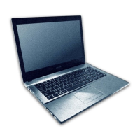
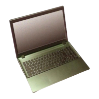
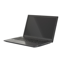
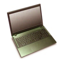
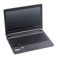
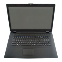
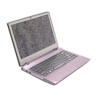
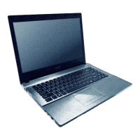
Identification of external parts on the top, sides, rear, and bottom views.

Mainboard Overview

Identification of key parts and connectors on the mainboard's top and bottom.

Chapter 2: Disassembly Procedures

Disassembly Overview and Tools

Introduction to disassembly, including necessary maintenance tools.

Connections and Maintenance Precautions

Description of internal connections and crucial maintenance precautions.

Disassembly Steps Summary

A reference table listing disassembly steps and their page numbers.

Removing the Battery

Step-by-step instructions for removing the notebook battery.

Removing the Keyboard

Step-by-step instructions for removing the notebook keyboard assembly.

Removing the Hard Disk Drive

Instructions for removing the hard disk drive for upgrade or replacement.

Removing the Optical Drive

Step-by-step instructions for removing the CD/DVD optical drive.

Removing System Memory (RAM)

Instructions for removing or replacing system memory modules.

Processor Removal and Installation

Detailed guide for removing and installing the CPU.

Removing the Fan Unit

Instructions for removing and replacing the computer's internal fan.

Removing Wireless LAN Module

Step-by-step instructions for removing the wireless LAN module.

Removing MSATA Module

Instructions for removing the MSATA storage module.

Removing the CCD

Step-by-step instructions for removing the CCD module.

Appendix A: Part Lists and Illustrations

Part List Illustration Location

Index table indicating where to find illustrations for component part numbers.

Appendix B: Schematic Diagrams Overview

Version Note

Important note regarding schematic diagram versions and service center contact.

System Block Diagram

High-level overview of the notebook's system architecture and connections.

Processor Schematics

Schematics for processor DMI, FDI, PEG, CLK, MISC, and DDR3 interfaces.

Memory Slot Schematics

Schematics detailing the DDR3 SO-DIMM memory slots.

Display Interface Schematics

Schematics for PS8625, Panel, Inverter, and VGA PCI-E interfaces.

Graphics Schematics

Schematics for VGA Frame Buffer interfaces (A and C).

VGA I/O and Related Schematics

Schematics for VGA I/O, NVVDD Decoupling, and CRT/Holes.

Chipset Interface Schematics (Lynx)

Schematics for Lynx Point interfaces (HDA, JTAG, SATA, LPC, SMBUS, SPI, CRT, LVDS, PCI, DISPLAY).

Connectivity Schematics

Schematics for 3G, WLAN, PCIE, CON, USB Charge, CCD, TPM, Power Con.

Component and Interface Schematics

Schematics for eSATA/USB3.0, LED, Card Reader, HDD, TP, Audio, USB, HDMI, RJ45.

Audio and Control Schematics

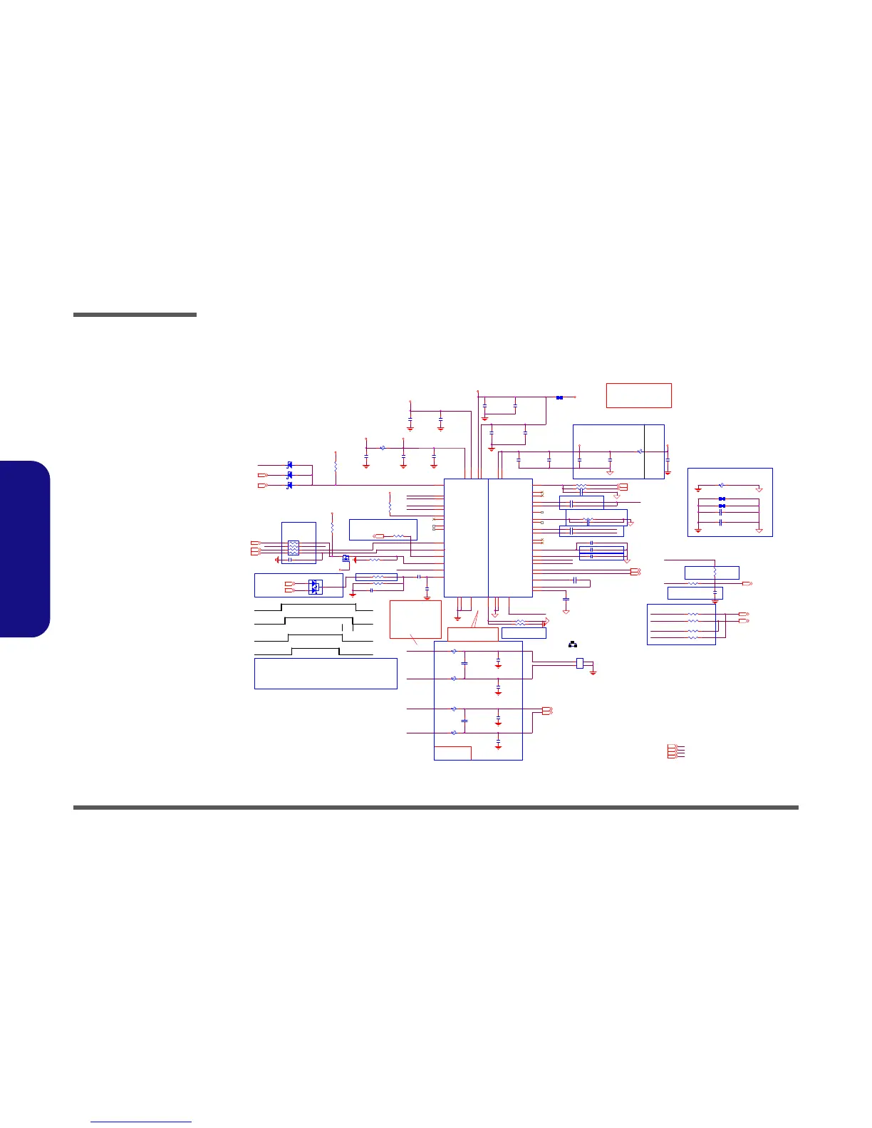
Schematics for the Audio Codec VT1802S and KBC-ITE IT8587.

Power Supply Schematics

Schematics for various power rails including 5VS, 3VS, 1.05V, VDD3/5, 1.5V, VCORE.

GPU and Power Management Schematics

Schematics for NVIDIA GPU power (N14P, NVVDD) and AC adapter/charger.

Board Level Schematics

Schematics for Audio Board, Power Switch Board, and ODD to HDD Board.

Appendix C: BIOS Update Procedures

BIOS Update Prerequisites

Required steps before starting the BIOS update process.

Download and Prepare BIOS Update Files

Instructions for downloading and unzipping BIOS files to bootable media.

Set Boot Order for BIOS Update

Configuring BIOS to boot from an external CD/DVD/USB drive.

Execute BIOS Flash and Restart

Using flash tools to update BIOS and restarting the computer.

Related product manuals