EasyManua.ls Logo

ComAp InteliGen NT BaseBox User Manual

ComAp InteliGen NT BaseBox
152 pages
To Next Page IconTo Next Page
To Previous Page IconTo Previous Page
Page #97 background imageLoading...
Page #97 background image
IGS-NT Communication Guide
97
7.4.3 Binary input - reading
Request: 01 03 00 02 00 01 25 CA
01 = Controller address
03
= Modbus function code (Read Multiple Registers
(page 133))
00 02
= Register address: Register number (40003) 40001
= 02 DEC => 02 HEX
00 01 = Number of registers (40003) = 01 DEC => 01 HEX
CA 25
= Check field calculation (page 143) (write LSB MSB
!)
Response: 01 03 02 00 0A 38 43
01 = Controller address
03
= Modbus function code (Read Multiple Registers
(page 133))
02 = Length of read data in Bytes (in HEX)
00 0A
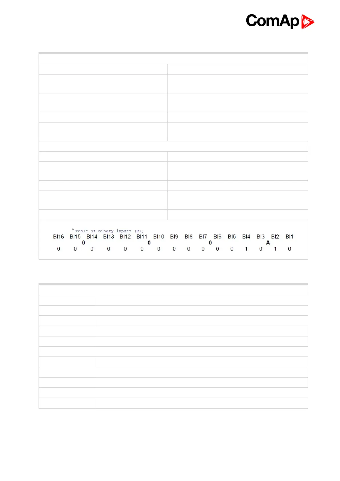
= Object data value (Binary input =
00000000000001010 i.e. BI2 and BI4 are set)*
43 38 = Check field calculation (page 143)
7.4.4 Password decode - reading
Request: 01 03 00 A0 00 02 C4 29
01 = Controller address
03 = Modbus function code (Read Multiple Registers (page 133))
00 A0 = Register address: Register number (40161) 40001 = 160 DEC => A0 HEX
00 02 = Number of registers (40161 and 40162) = 02 DEC => 02 HEX
29 C4 = Check field calculation (page 143) (write LSB MSB !)
Response: 01 03 04 68 73 90 00 7B 88
01 = Controller address
03 = Modbus function code (Read Multiple Registers (page 133))
04 = Length of read data in Bytes (in HEX)
68 73 90 00 = 68739000 HEX => 1752403968 DEC = > password decode is 1752403968
88 7B = Check field calculation (page 143)

Table of Contents

Question and Answer IconNeed help?

Do you have a question about the ComAp InteliGen NT BaseBox and is the answer not in the manual?

ComAp InteliGen NT BaseBox Specifications

General IconGeneral
ModelInteliGen NT BaseBox
Digital Inputs8
Analog Inputs4
Analog Outputs2
Operating Temperature-20 to +70 °C
Protection ClassIP20
Communication PortsRS232, RS485, Ethernet
Humidity95% non-condensing
Supported protocolsModbus, CAN, J1939
Storage Temperature-40 to +85 °C

Summary

Applications overview

Direct PC connection to Single gen-set

Methods for connecting a PC directly to a single gen-set for communication.

USB connection

Connecting controllers via USB for data transfer and configuration.

RS485 connection

Establishing communication using RS485 serial connections.

Direct PC connection to Multiple gen-sets

Methods for connecting a PC to multiple gen-sets for communication.

RS232/485 connection (I-LB+)

Connecting controllers via I-LB+ module using RS232/RS485.

USB connection via I-LB+ module

Connecting controllers via USB using the I-LB+ module.

Ethernet connection via IB-NT

Connecting controllers via Ethernet using the IB-NT bridge.

Ethernet connection (Direct)

Direct Ethernet connection for controller monitoring and configuration.

Monitoring Local on site - MODBUS

Describes local site monitoring using the MODBUS protocol.

ModBus - Multiple gen-sets

Explains Modbus communication for multiple gen-set systems.

RS232/RS485 – MODBUS (I-LB+)

Modbus communication via I-LB+ using RS232/RS485.

Ethernet - MODBUS (IB-NT)

Modbus communication via Ethernet using the IB-NT bridge.

Remote monitoring

Connection to Internet (Direct)

Setting up direct internet connection for controller monitoring.

Internet connection via AirGate

Using AirGate for internet connection without static IP addresses.

WebSupervisor

Overview of WebSupervisor system for monitoring and control.

Web interface

Accessing controller data and settings via a web browser.

Internet connection via cellular network

Connecting controllers via cellular networks using InternetBridge-NT.

Controller setup

Commands for IGS-NT

List and explanation of commands for IGS-NT controllers.

Commands for IM-NT

List and explanation of commands for IM-NT controllers.

Connection

Recommended CAN/RS485 connection

Guidelines for proper CAN and RS485 physical connections.

Communication

Modbus Communication

Overview of Modbus communication protocols and setup.

Examples of Modbus Communication

Practical examples of Modbus communication scenarios.

Modbus Connection

Modbus Step by Step

A step-by-step guide for establishing Modbus connection.

Important setpoints in the controller

Key controller settings required for Modbus communication.

Modbus communication via RS232 – single controller

Configuring Modbus communication over RS232 for a single controller.

Modbus communication via RS485

Configuring Modbus communication over RS485.

Related product manuals