K Series Service ManualRev A.
Theory 3-5
©1999 Crown International, Inc.
3.16 Crowbar Circuit
U13B and U13C form the DC protection comparator
circuitry. R191, R192 and C156 form a combination
resistive dividing and low pass filter networks. Sig-
nals below 8Hz (including DC voltages) cause the
combined outputs to become a logic low (–14V). This
logic level is inverted by the next comparator stage,
U7B. a logic high (0.6V) causes Q10 to conduct. Once
U7B switches states (logic high) U7A inverts this logic
level and latches the Fault circuit in the Crowbar dis-
abled condition. In order to clear this latched state
the amplifier must be first turned off.
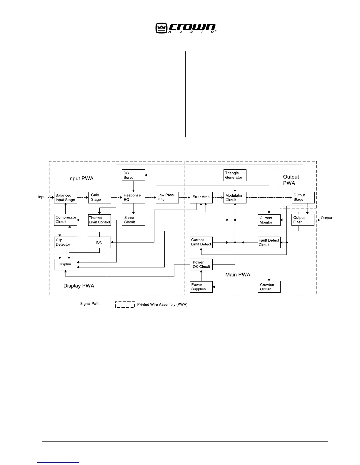
Figure 3.1 Amplifier Block Diagram
When the amplifier is turned on the line current con-
ducts through the R1 (power supply circuit diagram)
until the relay energizes. The relay primary is ener-
gized when Q8 is biased on. Q8 is biased on when
Q7 is biased off (high collector/emitter voltage). When
the relay closes R1 is bypassed allowing full power
supply energy available to the output stage. If Q10
conducts Q7 is biased on and Q8 is biased off. This
disables the power input relay.
 Loading...