K Series Service ManualRev A.
Maintenance 5-5
©1999 Crown International, Inc.
2. Clip the tie wrap which holds the orange and purple
wires to the Transformer Bracket.
3. Unplug the white wires from the Bridge PWA (P11,
P12 and P13). Note that the white wire with the black
ring attaches to P12.
4. Using a TX15 bit, remove the two screws which
hold the Transformer Bracket to the Front Panel.
5. Using a TX25 bit, remove the bolt which goes through
the center of the transformer. The plastic bracket can
now be removed.
6. While carefully lifting the transformer out of the
front panel, route the white wires underneath the Bridge
PWA. The transformer will now lift free of the front panel.
5.2.11 Display PWA Removal
The Front Panel Assembly must be removed in order
to remove the Display PWA.
1. Follow the instructions in Section 5.2.2. Supply
discharge is necessary to avoid circuit damage.
2. The two level control knobs on the front panel are
press fit onto the shafts. Remove these knobs.
3. Using a
7
/
16
-inch nut driver, remove the nuts on the
level control shafts. Also remove the flat washers.
Figure 5.4 Discharge Test Point
4. Lift the Display PWA out of the Front Panel Assem-
bly.
5.2.12 Bridge PWA Removal
The Front Panel Assembly must be removed in order
to remove the Bridge PWA.
1. Follow the instructions in Section 5.2.2. Supply
discharge is necessary to avoid circuit damage.
2. Unplug the white transformer wires from the PWA.
Note that the white wire with the black ring goes to
P12.
3. Using a T20 bit, remove the two screws that hold
the bridge rectifiers to the front panel. The screws have
bellville washers. When installing the screws with the
washers, make sure the cupped side of the washer is
toward the bridge.
4. Using a T20 bit, remove the screw in the center of
the PWA.
5. The bridge assembly will now lift out of the front
panel. When installing it back into the front panel,
make sure there is thermal heatsink compound between
the bridges and the front panel.
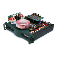
Bridge PWA
Output PWA
Output PWA
Power Transformer
Display PWA
Control PWA
Main PWA
Input PWA
Figure 5.4 PWA Layout
Line Filter PWA
 Loading...