K Series Service ManualRev A.
Maintenance 5-3
©1999 Crown International, Inc.
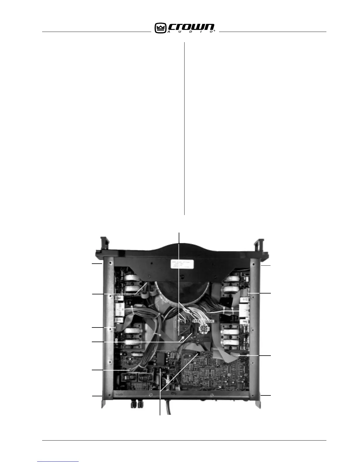
5.2.4 Front Panel Assembly Removal
The front panel assembly is removed to access the
Power Switch, Display PWA, Bridge PWA and the Power
Transformer.
1. Follow the instructions in Section 5.2.2. Supply
discharge is necessary to avoid circuit damage.
2. Using a TX 15 bit, remove two screws on each side
of the amp located directly behind the rack ears. See
Figure 5.2.
Item G
3. Remove the four TX 15 screws along the top front of
the amplifier.
4. Unplug the main wiring harness from the Bridge
PWA. See Figure 5.2.
Item H
5. Remove the P1 ribbon connector from the Input
PWA. See Figure 5.2.
Item D
6. Remove the P5 and P6 transformer wire connec-
tors, and P10, P11, P12 and P13 switch wires from the
Control PWA. See Figure 5.2.
Item I
7. The Front Panel Assembly will now come off of the
amplifier. Pull on the front panel handles while secur-
ing the chassis of the amplifier. Be careful of the wires
and cables that will come with the assembly. When
reinstalling the Front Panel, make sure the capacitors
on the Bridge PWA clear the aluminum heat sink and
the Output PWA.
5.2.5 Input PWA Removal
The Back Panel Assembly must be removed to gain
access to the Input PWA.
1. Follow the instructions in Section 5.2.2. Supply
discharge is necessary to avoid circuit damage.
2. Remove the P2 ribbon cable from the Input PWA.
3. Using a #1 Phillips bit, remove the four screws that
hold the two female XLR jacks on the back panel.
4. Using a
5
/
8
-inch nut driver, remove the two plastic
nuts that hold the
1
/
4
-inch input jacks in place.
5. Using a TX15 bit, remove the two screws on the
back panel that hold the Input PWA in place.
6. Locate the plastic board stand–off between the Main
and Input PWAs. Using your fingernail or pliers, press
the release tab on the stand–off while gently lifting the
Input PWA off the stand–off.
7. While guiding the input jacks out of the holes in the
back panel, slowly lift the PWA out of the assembly.
5.2.6 Main PWA Removal
The Back Panel Assembly must be removed to gain
access to the Main PWA.
1. Follow the instructions in Section 5.2.2. Supply
discharge is necessary to avoid circuit damage.
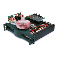
Figure 5.2 Bottom View
A
B
C
D
E
F
G
H
I
A
F
G
 Loading...