K Series Service ManualRev A.
Maintenance 5-1
©1999 Crown International, Inc.
5.1 Where to Begin
Effective repair involves three basic steps: 1) Deter-
mine the symptom(s) of the problem; 2) Identify the
cause(s) of the symptom(s); 3) Repair the unit to elimi-
nate the cause(s). To determine the symptoms, you
will want to get as much information from the user as
possible. Get as much information as you can about
the system and how the amplifier is used. There is
always the possibility that the problem will show up
only if used in a specific way.
Once you have all the information about the symptom(s),
it is time to inspect the amplifier. A careful visual in-
spection is valuable for most problems which you may
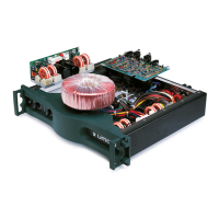
encounter. To inspect the inside of the amplifier remove
the cover as described in Section 5.2.1.
Begin the inspection by looking for anything which
appears abnormal, like loose connectors, broken wires
and burnt or visibly damaged components. Inspect
the printed circuit assemblies for broken traces and
loose connections. Be thorough. The time you spend
visually inspecting the amp is time well spent.
5.2 Disassembly for Inspection & Service
The extent of disassembly required will depend upon
the extent of inspection and service required.
NOTE: TO AVOID THE RISK OF ELECTRIC SHOCK,
TURN OFF AND UNPLUG THE AMPLIFIER FROM
THE AC POWER OUTLET BEFORE DISASSEMBLY
OR REASSEMBLY IS ATTEMPTED.
5.2.1 Bottom Cover Removal
To remove the cover of the amplifier you will need a
#15 torx bit (TX15). After the cover is removed, and
before any internal cables are disconnected, discharge
the supplies. See Section 5.2.2.
1. Turn the amplifier on its side on your workbench.
The only access to the inside of the amplifier is the
bottom cover.
2. Using the TX15 bit, remove the 14 screws around
the perimeter of the cover.
3. The cover lifts straight up after the screws are re-
moved.
4. Vacuum out any metal particles in the unit that are a
result of the lock washers digging into the chassis.
The cover on early units may appear to be symetrical
but it’s not. When installing it onto the unit, make sure
there is no gap between the front edge of the cover
and the lip of the front panel extrusion. If installed back-
wards, there will be an
1
/
8
-inch gap at the front, and an
1
/
8
-inch overhang out the back of the unit.
5 Maintenance
WARNING
Amplifier components are ESD sensitive.
When servicing the amplifier, the technician
must have approved ESD protection. Proper
grounding straps and test equipment are
required. Failure to use proper protection
will result in component failure.
WARNING
Before unplugging or plugging in any con-
nectors or wires in the amplifier, discharge
the power supplies. See section 5.2.2 for
instructions. Failure to do so will result in
circuit failure.
 Loading...