K Series Service Manual Rev A.
5-2 Maintenance
©1999 Crown International, Inc.
5.2.2 Power Supply Discharge
Before any connectors and PWAs are removed, the
Power Supplies need to be discharged. Follow these
simple steps.
1. Make sure the amplifier is unplugged from the AC
power source.
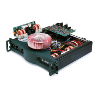
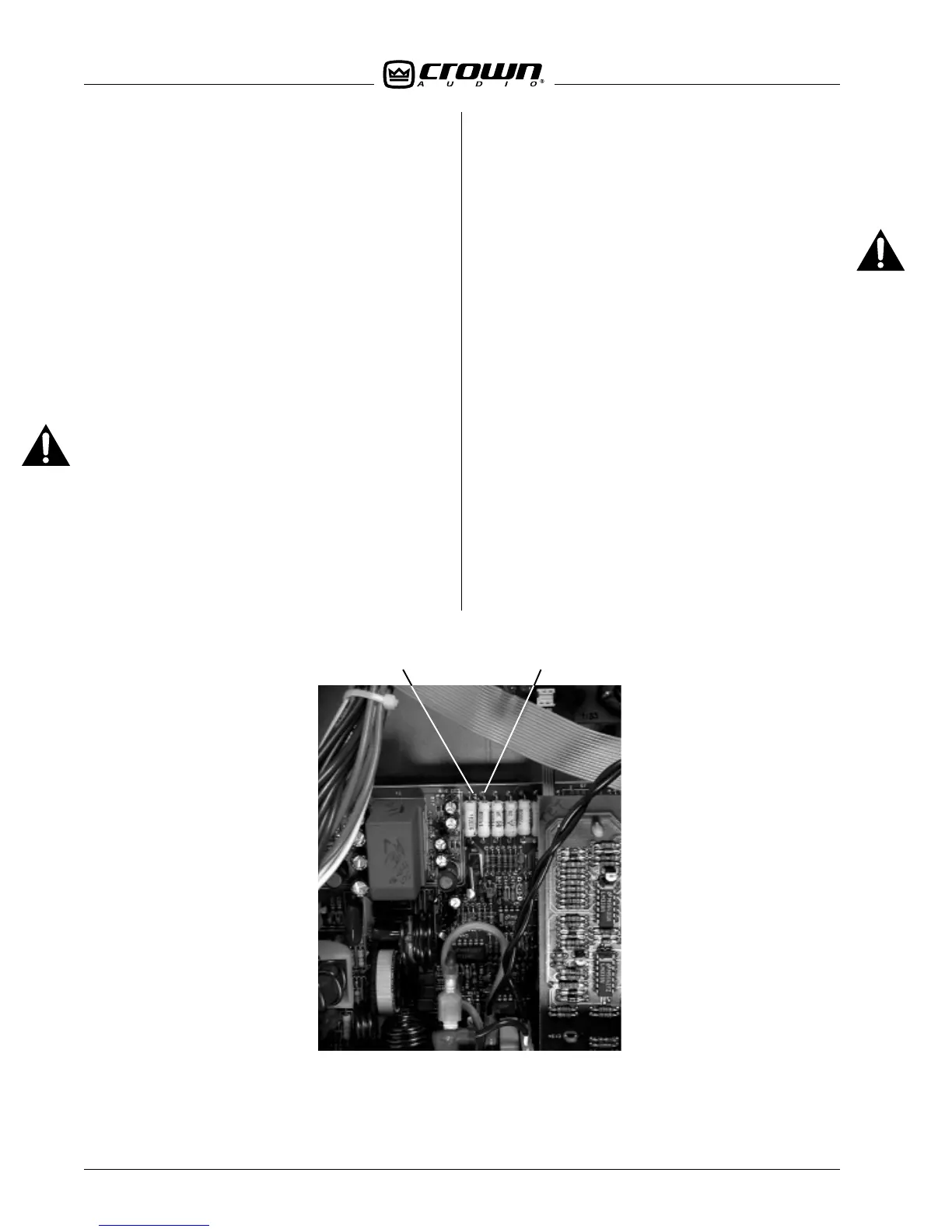
2. Locate Test Point 1 (TP1) on the Main PWA. See
Figure 5.1.
3. With a flat blade screwdriver or another metal ob-
ject, short TP1 to the nearest resistor pad. This resistor
is the second one from the end of a row of seven 3W
resistors. Once the short is made you do not have to
hold the screwdriver in place. The initial short triggers
a latching triac circuit which discharges the supplies.
4. Wait a few seconds before attempting to disas-
semble the amplifier.
Caution: the three-watt resistors will become hot as
the power supplies discharge.
5.2.3 Back Panel Assembly Removal
The back panel assembly is removed to access the
Input and Main PWAs.
1. Follow the instructions in Section 5.2.2. Supply
discharge is necessary to avoid circuit damage.
2. Remove the aluminum shield by removing the two
screws on the rear and the one on the control board.
Note: This shield is not used on early non-CE units.
3. Using a TX15 bit, remove the two screws on each
side of the amp that hold the rear supports. See Fig-
ure 5.2.
Item A
4. Remove the five TX15 screws along the top rear of
the amplifier.
Caution: These screws are shorter than the other
cover screws and must be reinstalled in the same
location or Main PWA will be shorted to chassis.
5. Remove the two TX15 screws on the Main PWA.
See Figure 5.2.
Item B
6. Unplug the black and white wires (P8 & P9) and the
ribbon cable (P4) from the Control PWA. See Figure
5.2.
Item C
7. Unplug the P1 ribbon cable from the Input PWA.
See Figure 5.2.
Item D
8. Unplug the main wiring harness from the Main PWA.
See Figure 5.2.
Item E
9. Remove the necessary tie wraps and unplug the
ribbon cables from the Output PWAs. See Figure 5.2.
Item F
10. Gently slide the back panel assembly straight out
the back of the amplifier. Note that the PC cards slide
in the rails formed in the aluminium heatsink. Be care-
ful of the wires and cables that will come with the as-
sembly.
Figure 5.1 Discharge Test Point
TP1 Resistor Pad
 Loading...