EasyManuals Logo

D-Link DGS-1510- 52XMP User Manual

D-Link DGS-1510- 52XMP
69 pages
To Next Page IconTo Next Page
To Previous Page IconTo Previous Page
Page #16 background imageLoading...
Page #16 background image
DGS-1510 Series Gigabit Ethernet SmartPro Switch Hardware Installation Guide
16
LED Description
assigned as the stacking Master. “h“ means the device was selected
to be the Backup Master. A “G” is displayed when the Safeguard
Engine feature enters the exhausted mode. An “E” is displayed when
an error was found during the system self-test.
For more information about LED Indicators, refer to LED Indicators.
Rear Panel Components
On the rear panel of the Switch there are an AC power socket, an electrical grounding point, and a
security lock.
Figure 1-19 Rear panel view of a DGS-1510-20 Switch
Figure 1-20 Rear panel view of a DGS-1510-28 Switch
Figure 1-21 Rear panel view of a DGS-1510-28P Switch
Figure 1-22 Rear panel view of a DGS-1510-28X Switch
Figure 1-23 Rear panel view of a DGS-1510-28XMP Switch
Figure 1-24 Rear panel view of a DGS-1510-52 Switch

Table of Contents

Questions and Answers:

Question and Answer IconNeed help?

Do you have a question about the D-Link DGS-1510- 52XMP and is the answer not in the manual?
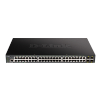
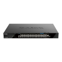
D-Link DGS-1510- 52XMP Specifications

General IconGeneral
ModelDGS-1510-52XMP
CategorySwitch
PoE StandardIEEE 802.3af/at
PoE Budget370W
Switching Capacity176 Gbps
Forwarding Rate130.95 Mpps
MAC Address Table Size16K
VLANs4K
Jumbo Frame Support9KB
Ports48 x 10/100/1000BASE-T, 4 x 10G SFP+
Dimensions440 x 44 x mm
Operating Temperature0 to 45 °C
Storage Temperature-40 to 70 °C
Standards ComplianceIEEE 802.3, 802.3u, 802.3ab, 802.3z, 802.3x, 802.3af, 802.3at, 802.1D, 802.1w, 802.1s, 802.1Q, 802.1p
Humidity5% to 95% non-condensing

Related product manuals