DGS-3130 Series Layer 3 Stackable Managed Switch Hardware Installation Guide
32
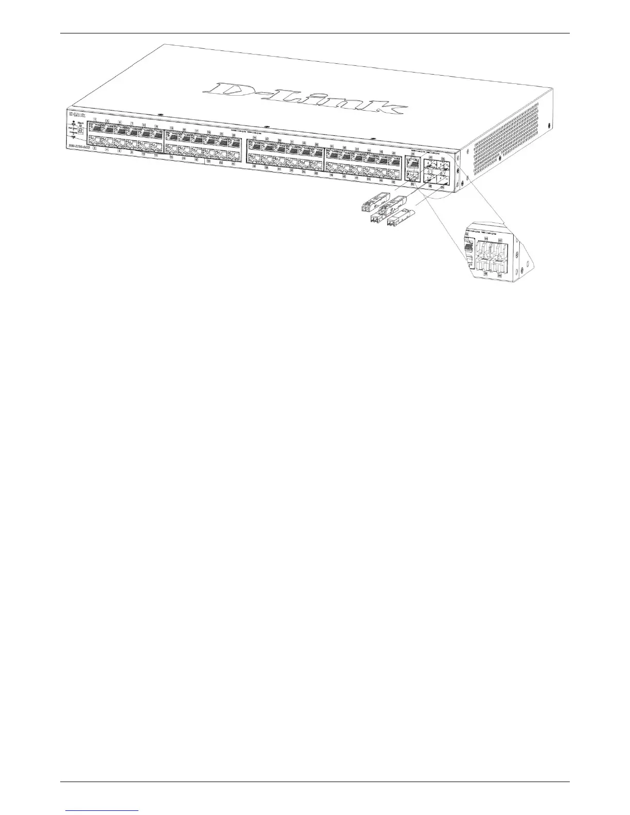
Figure 3-4 Inserting transceivers into the transceiver ports
The SFP+ ports also support other transceiver form factors like SFP and SFP+ transceivers. A complete list of
SFP/SFP+ transceivers, compatible with this switch, can be found the SFP Ports and SFP+ Ports sections in
Appendix A - Technical Specifications at the end of this document.
Power On (AC Power)
Plug one end of the AC power cord into the power socket of the Switch and the other end into the local power source
outlet. After the system is powered on, the LED will light green to indicate that the system is booting up.
Power Failure (AC Power)
In the event of a power failure, just as a precaution, unplug the power cord from the Switch. After the power returns,
plug the power cord back into the power socket of the Switch.
Installing Power Cord Retainer
To prevent accidental removal of the AC power cord, it is recommended to install the power cord retainer together with
the power cord.
1. With the rough side facing down, insert the tie wrap into the hole below the power socket.
 Loading...