ENGLISH
68
GB
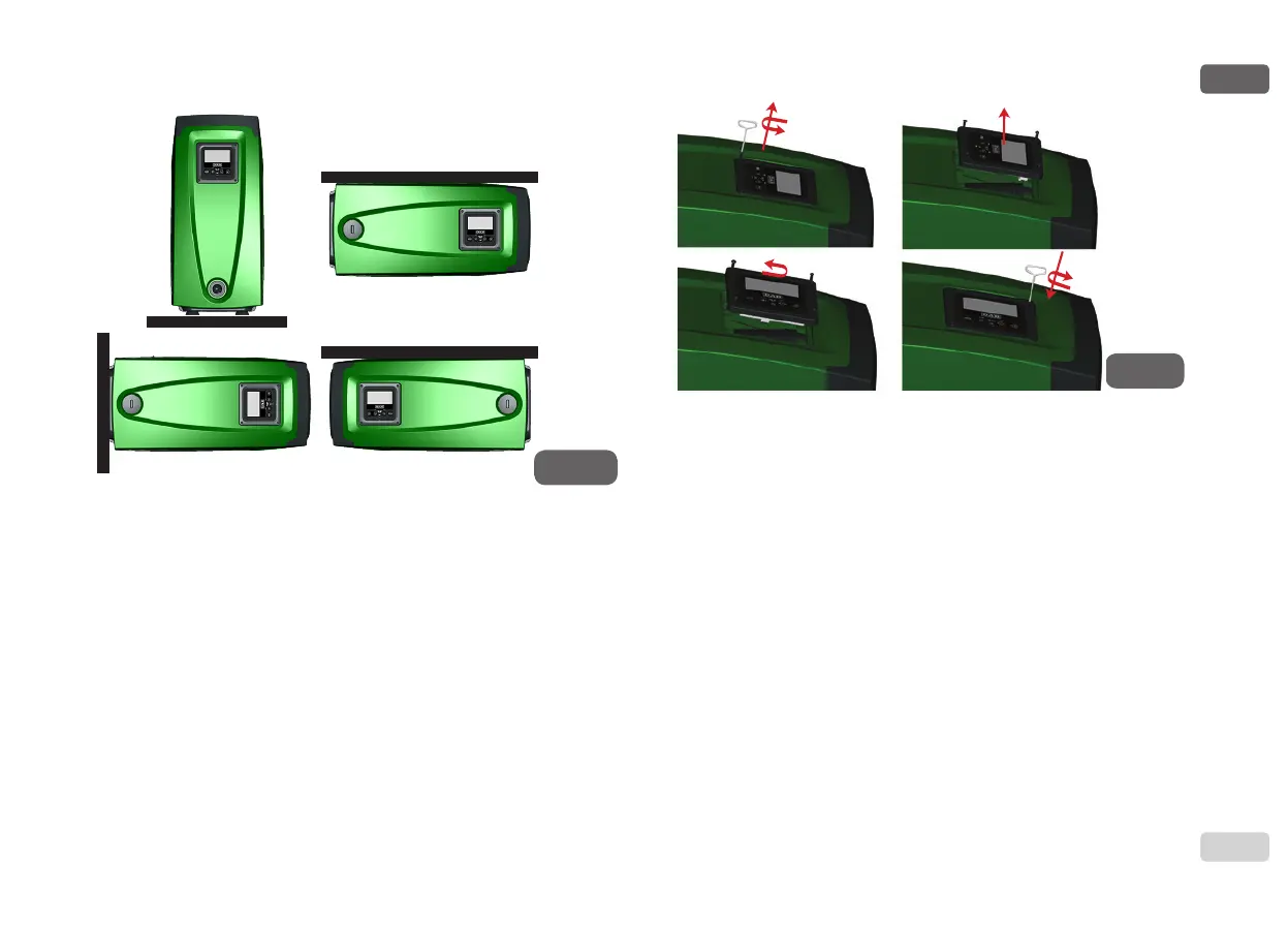
• Disengage the 4 screws at the corners of the panel using the hex
wrench provided with the accessory tool.
• Do not remove the screws, just disengage them from the thread
on the product body.
• Be careful not to drop the screws into the system.
• Move the panel away, taking care not to pull on the signal trans-
mission cable.
• Reposition the panel in its seat at the preferred angle taking care
not to pinch the cable.
• Tighten the 4 screws with the wrench.
2.2.3 Loading Operation
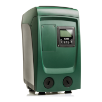
Installation above head and below head
With reference to its position with respect to the water to be pumped, the instal-
lation of the system may be dened “above head” or “below head”. In particular
the installation is dened “above head” when the pump is placed at a level
higher than the water to be pumped (e.g. pump on the surface and water in
a well); vice versa it is “below head” when the pump is placed at a level lower
than the water to be pumped (e.g. overhead cistern and pump below).
Installation “above head”: with the aid of the accessory tool (Fig.3_point 5) or
with a screwdriver, remove the lling cap which, for the horizontal conguration,
is the one on Face F (Fig.1). Fill the system with clean water through the load-
ing door, taking care to let the air out. The quantity of water with which to ll the
system must be at least 1.5 litres. It is recommended to t a non-return valve at
the end of the suction pipe (foot valve) so as to be able to ll it quickly too dur-
ing the loading operation. In this case the quantity of water necessary for the
loading operation will depend on the length of the suction pipe (1.5 litres + …).
Installation “below head”: if there are no check valves between the water de-
posit and the system (or if they are open), it loads automatically as soon as it is
allowed to let out the trapped air. So slackening the lling cap (Face F - Fig.3)
enough to vent the air allows the system to load completely. To slacken the cap,
Figure 11
x4
x4
Figure 10
 Loading...