ENGLISH
GB
73
PB
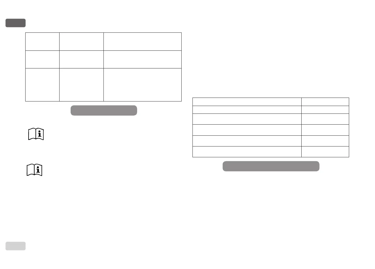
Blockage due to line
voltage outside speci-
cations
- It is reset when it returns to a specic
voltage
OT
Blockage due to over-
heating of the power
stages
-It is reset when the temperature of
the power stages returns within the
specications.
OC
Blockage due to motor
overload
- One attempt every 10 minutes for a
total of 6 attempts
- One attempt every hour for a total of
24 attempts
- One attempt every 24 hours for a total
of 30 attempts
5 - INVERTER ELECTRONIC CONTROL AND USER INTERFACE
The inverter makes the system work at constant pressure. This
regulation is appreciated if the hydraulic plant downstream from
the system is suitably sized. Plants made with pipes with too
small a section introduce load losses that the equipment cannot
compensate; the result is that the pressure is constant on the
sensors but not on the utility.
Plants that are excessively deformable can create the onset of
oscillations; if this occurs, the problem can be solved by adjust-
ing the control parameters “GP” and “GI” (see par 7.6.4 - GP:
Proportional gain coefcient and 7.6.5 - GI: Integral gain coef-
cient).
5.1 - Operation with control unit
e.sybox, alone or in a pumping unit, may be connected by means of wire-
less communication to a remote unit referred to below as a control unit.
Depending on the model, the control unit offers a variety of functions.
The possible control units are:
• e.sylink
Table 3: Self-reset of blockages
Combining one or more e.syboxes with a control unit allows the use of:
• Digital inputs
• Relay outputs
• Remote pressure sensor
• Ethernet network connection
Below, the combination of functions listed above, made available by the
various types of control unit, will be referred to as “control unit functions
5.1.1 - Functions made available by control units
The functions made available are specied in Table 4, Functions made
available by control units
Functions e.sylink
Opto-isolated digital inputs
•
Output relay with NO contact
•
Remote pressure sensor
•
Network connection
5.1.2 - Electrical connections of utility inputs and outputs
See control unit manual.
5.1.3 - Safety mode operation
When using the input or remote sensor functions, in the event of a commu-
nications downage or control unit error, the e.sysbox and control unit will
switch to safety mode, adopting the conguration considered least dam-
aging. When safety mode comes into operation, a ashing icon showing a
cross inside a triangle appears on the display.
The way in which the e.sysbox responds to a communications downage is
explained in the table below.
Tab. 4: Functions made available by control units
 Loading...