Service manual CP-785A
- 34 -
5-3 Source switching
The TDA936x has only one external video input, the external video switching circuit made with
Q504, Q505 and Q508 allows 2 external video signal inputs. The switching command can be
the µ-Controller pin 8 when the software takes control of the video source.
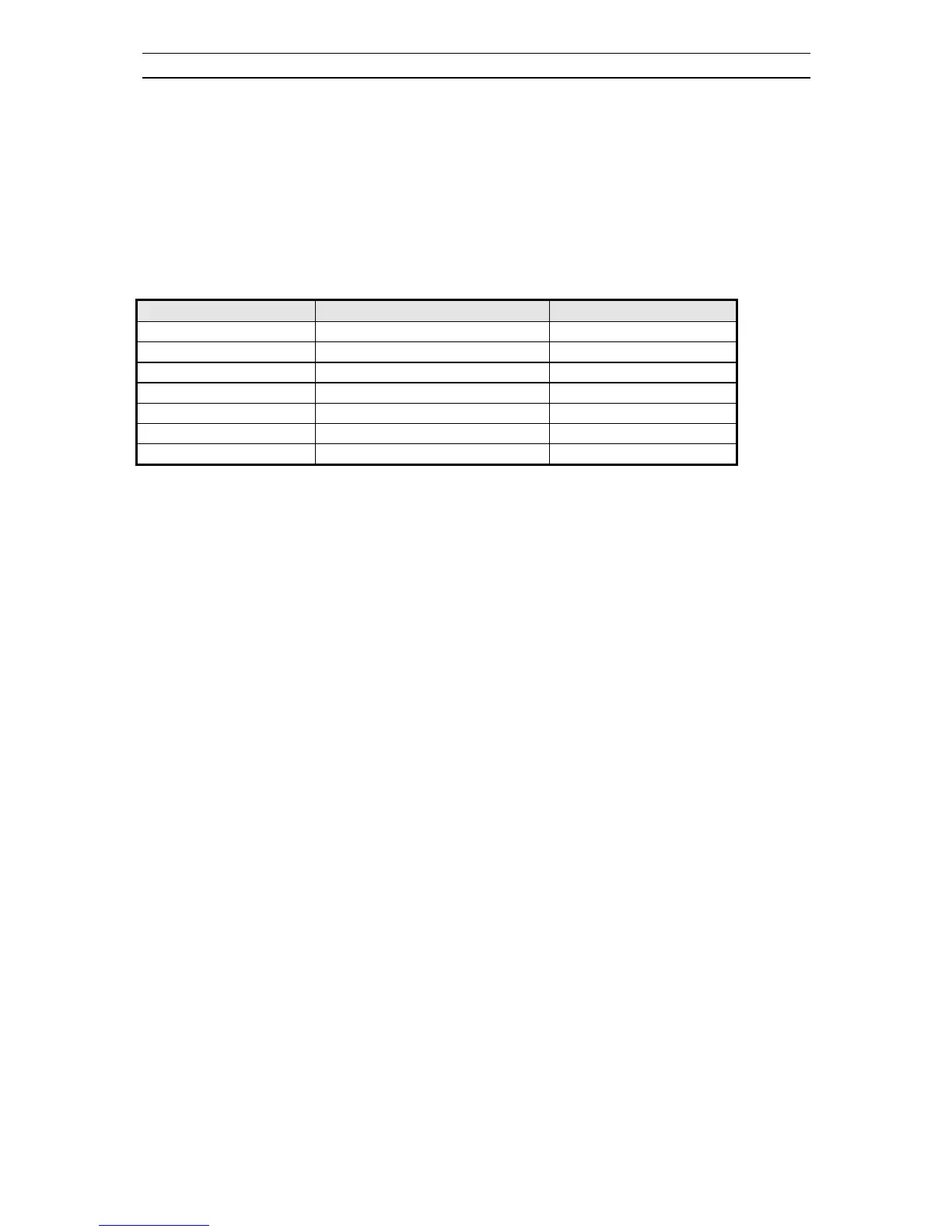
The µ-Controller pin 8 is automatically configured by the controlling software (See table below).
TV mode
µ
-Controller pin 8 Status
Level
RF auto Input - High Impedance < 1V
RF Forced Input - High Impedance not defined
AV 1 Input - High Impedance > 2.0 V
AV 1 Output - Push Pull Max. 3.3V
AV 2 Output - Push Pull < 0.2 V
SVHS Output - Push Pull < 0.2 V
The controlling software via I2C bus selects the signal source :
- Video signal from tuner ( Pin 40 ).
- External video ( SCART 1 or 2 ) depending on Q508 base level.
- External SVHS from SCART 2.
The sound source switching is done in the MSP3415D ( I601 ), by the µ-Controller via I2C bus.
Fast R, G, B insertion : The external R, G, B insertion needs a fast switching and cannot be controlled
by the software ( instruction cycle of 1µ sec ). The fast switching pin 16 of SCART 1 is directly
connected to the TV processor pin 45 ( Fast blanking input ). The display is synchronised with the
selected video source, i.e. to get stable R, G, B inserted signal they must be synchronised with the
selected video source. The controlling software only enable or disable ( AV2, SVHS, or Forced RF
source selected ) fast blanking.
5-4 µ-Controller I/O pin configuration and function
The I/O pins of the µ-Controller can be configured in many way. All port functions can be individually
programmed by use of the SFR registers.
Each I/O port pin can be individually programmed in these configurations :
Open drain
In this mode, the port can function as in and output. It requires an external pull-up resistor. The
maximum allowable supply voltage for this pull up resistor is +5V.
So in this mode it is possible to interface a 5 Volt environment like I2C while the µ-Controller has a 3.3
Volt supply.
Push-Pull
The push pull mode can be used for output only. Both sinking and sourcing is active, which leads to
sleep slopes. The levels are 0 and Vddp, the supply voltage 3.3Volts.
 Loading...