Service manual CP-785A
- 43 -
5-9 TV start-up, TV normal run and stand-by mode operations
5-9-1 TV start-up operations
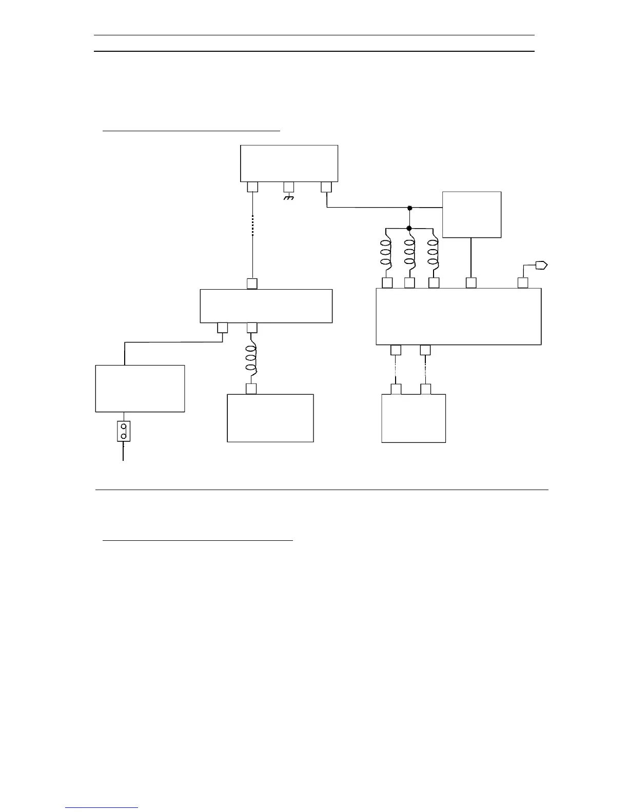
* Schematic diagram for start-up operations
I823 REG 3.3V
IN
GND
OUT
1
2 3
RESET
PULSE
CIRCUIT
IN
OUT
Vddp
Start-up operations
* TV start-up and microcontroller initialization
- When SW801 power switch is pushed, main AC voltage is applied to T801 transformer (after
rectification by D801...D804 diodes). Then, T801 SMPS transformer starts operating and supplies
DC voltage to I823 (3.3V regulator).
- This regulator provides 3.3V DC voltage to I501 microcontroller power supply pins (pins 54, 56, 61)
and to the reset pulse circuit which provides reset pulse to I501 microcontroller reset pin (pin 60).
- Then, the microcontroller starts its initialization. Its power pin (pin 63) is set to high which allows
delivery of power supply voltages (123V, 8V, 5V...). At this step, all IC’s start working but no picture
appears on screen: I501 IC doesn’ t provide horizontal drive voltage.
- Then, the microcontroller consults I702 EEPROM via I2C bus to know the last TV set mode (normal
run mode or stand-by mode ) before switching off.

 Loading...