IO-DAPPS www.daikinac.com 4
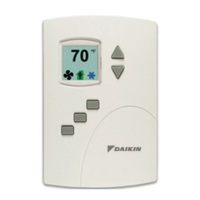
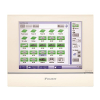
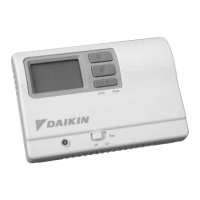
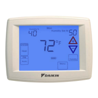
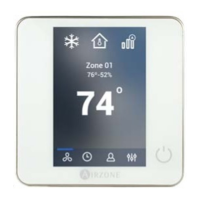
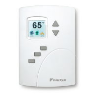
User Interface
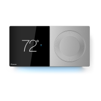
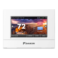
The user interface is a color display and has ve push buons.
Through the menu driven display, an operator can do the following.
• Add or change user passwords
• Change setpoints
• Set BACnet addressing
• Set up and commission the installaon
• Congure any available opons
Security
Separate passwords for users and controls technicians.
Display Type
• 128 × 128 pixels
• Acve color LCD with LED back lighng
• 1.00 × 1.04 inches (25 × 26 mm)
Inputs and Outputs
All inputs and outputs are pre-programmed and applicaon specic.
No eld conguraon is required for most installaons. For details
on input and output connecons see the secon Applicaon
Drawings on page 31.
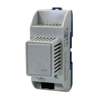
Analog Inputs
Analog inputs represent BACnet analog input objects and are
congured for discharge air temperature, remote temperature
sensor, water temperature sensor, and fan status. Not all input
sensors are applicable or required for all models.
• Sensors are automacally detected
• Inputs accept industry-standard 10,000Ω, Type II
thermistor sensors
• Input overvoltage protecon up to 24 volts AC, connuous
• 12-bit analog-to-digital conversion
• Short-circuit protected
• Loads up to 10 mA at 0-12 volts DC
• 8-bit PWM digital-to-analog conversion
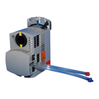
Relay Outputs
Relay outputs are congured to represent BACnet binary objects.
The outputs control ON/OFF valves, speeds for three-speed fans, fan
start circuits, or other equipment that requires an on or o input signal.
• All relay outputs are normally open, SPST, Form “A” relays
• 1 Ampere maximum per relay at 24 volts AC or DC for each output.
Maximum for all relay outputs is 3 amperes (72VA)
Connectors
• Screw terminal block mounted to backplate
• Wire size 14-22 AWG
Communicaons – BACnet™ MS/TP
• Integral peer-to-peer BACnet MS/TP network communicaons
• Network speeds from 9600 to 76,800 baud
• Front panel congurable device instance, MAC address, and baud
• Automac baud detecon
• Screw terminal block mounted to backplate; wire size 14-22 AWG
• Meets or exceeds ANSI/ASHRAE BACnet Standard 135-2008 for
Applicaon Specic Controllers
Accuracy
Type Thermistor
Accuracy ±0.36°F (±0.2°C)
Resistance 10,000Ω at 77°F (25°C)
Operang Range 48 to 96°F (8.8 to 35.5°C)
Regulatory
• UL 916 Energy Management Equipment
• FCC Class A, Part 15, Subpart B and complies with
Canadian ICES-003 Class B
• SASO PCP Registraon KSA R-103263
This device complies with part 15 of the FCC Rules. Operaon is subject
to the following two condions: (1) This device may not cause harmful
interference, and (2) this device must accept any interference received,
including interference that may cause undesired operaon.
• This equipment has been tested and found to comply with the
limits for a Class A digital device, pursuant to part 15 of the FCC
Rules. These limits are designed to provide reasonable protecon
against harmful interference when the equipment is operated in
a commercial environment. This equipment generates, uses, and
can radiate radio frequency energy and, if not installed and used
in accordance with the instrucon manual, may cause harmful
interference to radio communicaons. Operaon of this equipment
in a residenal area is likely to cause harmful interference in which
case the user will be required to correct the interference at his
own expense.
• The FCC responsible party is KMC Controls, Inc. and may be
contacted at 19476 Industrial Drive, New Paris, IN 46553
Specicaons
 Loading...