13
FOR MODULAR BLOWER:
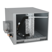
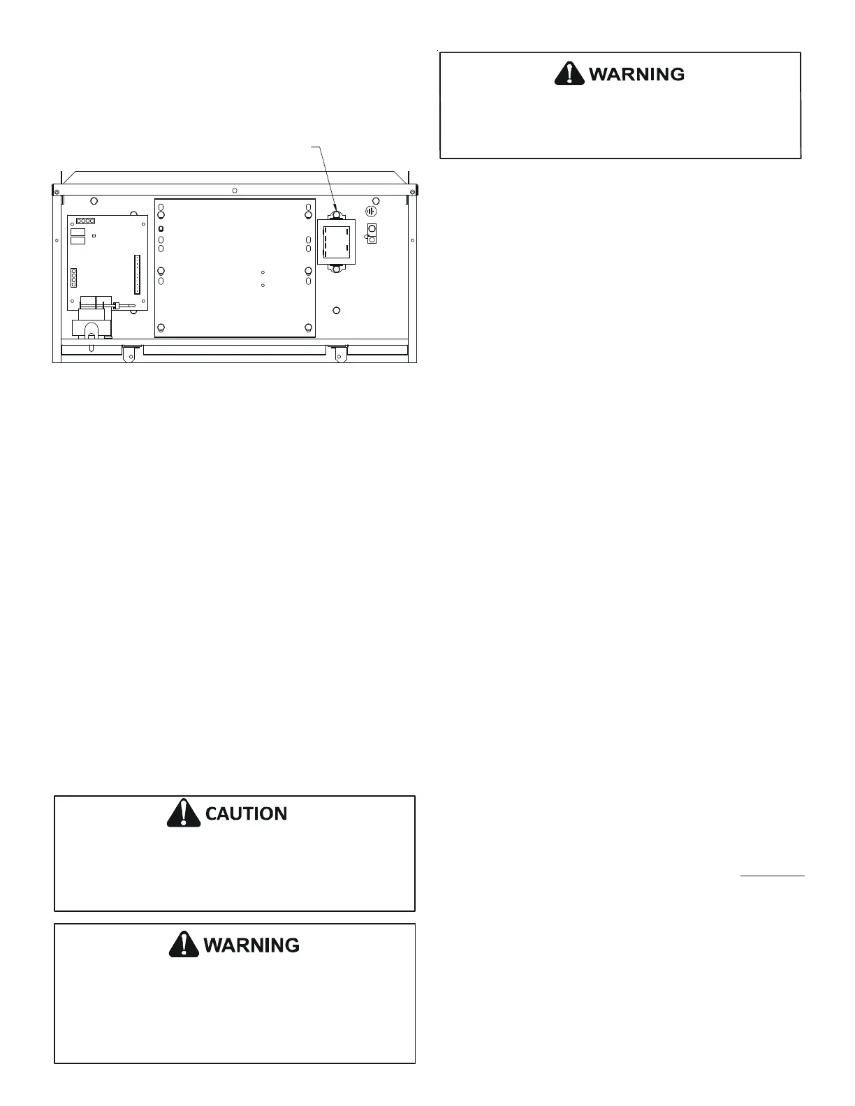
Remove the screw located on the control deck that is shown in
Figure 23 and affix the PCB transformer with the removed screw
and a screw hole. Then secure another screw hole of the PCB trans-
former using (1) field supplied, self-drilling screw.
USE THIS STOCK SCREW
Figure 23
11.6 WIRING TRANSFORMER AND PCB
IMPORTANT: When wiring PCB power supply to PCB transformer,
an insulated bushing (field supplied) must be installed in the fur-
nace or modular blower cabinet wall. Wiring must pass through
bushing to interior of cabinet . DO NOT ALLOW WIRING TO PASS
ALONG AREAS WHERE WIRING IS EXPOSED TO ABRASIVE METAL
EDGES. DO NOT ALTER BLOWER DECK.
To power PCB transformer: Use high voltage red and black wires
provided in transformer kit. Route red/black transformer power
supply to PCB transformer from field wiring. Power and ground
wiring for cased coil: Use accompanied yellow, purple and green
wiring harness.
Communication wiring: Use accompanied black, grey, red and blue
wire harness.
DO NOT POWER TO TR1/TH1 TERMINAL OF PCB WITH FACTORY
INSTALLED FURNACE R/C THERMOSTAT POWER INSTEAD OF PCB
TRANSFORMER.
NOTE: Create wire trap on outside of cabinet wall before passing
into cabinet. The wire trap must remain below the insulated wire
bushing location to prevent moisture intrusion into furnace or
modular blower cabinet and onto electrical components.
Outside the cased coil, do not route transmission wiring together
with other electrical wiring. Keep the transmission wiring at least
2 in. (50mm) away from the power wiring and other electrical
wiring. Effects of electrical interference (external noise) may
result in malfunction and breakdown.
Use only specified wire and connect to terminals tightly. Be
careful that wires do not place external stress on terminals. Keep
wire in neat order; not to obstruct other equipment. Make sure
that the control panel cover is closed tightly. Incomplete
connections could result in overheating, and in worse cases,
electric shock or fire.
When doing the wiring, make sure the wiring is neat and does not
not touch sharp edge of sheet metal and does not cause the
control panel to stick up, and then close the cover firmly. When
attaching the control cover, make sure you do not pinch any
wires.
12 COMFORTNET™ SYSTEM
12.1 Overview
The ComfortNet™ system is a system that includes a ComfortNet
compatible cased coil and outdoor unit with a communicating
thermostat.
System may ONLY be installed using ComfortNet thermostat with
model number CTK04AE or newer as part of the digital communi-
cating system or another Daikin approved communicating ther-
mostat.
A ComfortNet heating/air conditioning system differs from a non-
communicating/traditional system in the manner in which the
indoor unit, outdoor unit and thermostat interact with one an-
other. In a traditional system, the thermostat sends commands to
the indoor and outdoor units via analog 24 VAC signals. It is a one-
way communication path. The indoor and outdoor units typically
do not return information to the thermostat.
On the other hand, the indoor unit, and thermostat comprising a
ComfortNet system “communicate” digitally with one another. It
is now a two-way communications path. The thermostat still
sends commands to the indoor and outdoor units and may also
request and receive information from both the indoor and out-
door units. This information may be displayed on the ComfortNet
thermostat. The indoor and outdoor units also interact with one
another. The outdoor unit may send commands to or request
information from the indoor unit. This two-way digital communi-
cations between the thermostat and subsystems (indoor/out-
door unit) is the key to unlocking the benefits and features of the
ComfortNet system.
12.2 Thermostat Wiring
NOTE: Refer to section 11. ELECTRICAL WIRING WORK for 24 volt
line connections to the cased coil.
NOTE: You should use a DAIKIN approved thermostat (CTK04AE or
newer). Not approved for use with a CTK01, CTK02, CTK03,
CTK04AD or older.
NOTE: A removable plug connector is provided with the control to
make thermostat wire connections. This plug may be removed,
wire connections made to the plug, and replaced. It is STRONGLY
recommended that you do not connect multiple wires into a
single terminal. Wire nuts are recommended to ensure one wire
is used for each terminal. Failure to do so may result in intermit-
tent operation.
Typical 18 AWG thermostat wire may be used to wire the system
components. However, communications reliability may be im-
proved by using a high quality, shielded, twisted pair cable for the
data tranmission lines.
 Loading...