14
12.3 Two-Wire Outdoor and Four-Wire Indoor Wiring
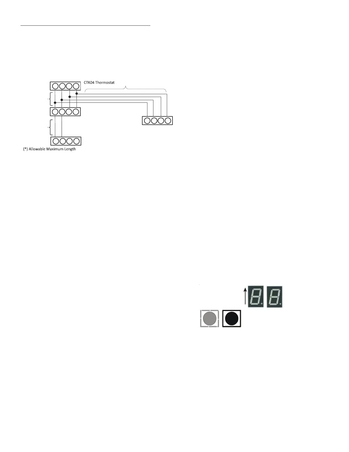
Typical wiring will consist of two wires between the indoor unit
and outdoor unit and four wires between the indoor unit and
thermostat. Figure 24 shows the required wires are: data lines, 1
and 2; “R” (24 VAC hot) and “C” (24 VAC common).
CT™ Compatible
Gas Furnace or
Modular Blower
Integrated Control Module
CT™ Compatible Outdoor Unit
Integrated
Control Module
12RC
12RC
12RC
12RC
CT™ Compatible
Case Coil
Integrated
Control Module
Allowable Maximum Length
(a)
250 ft.
(*)
(b)
(b)(a)
+
=125 ft.(*)
Figure 24
13 MISCELLANEOUS START-UP CHECKLIST
• Prior to start-up, ensure that all electrical wires are prop-
erly sized and all connections are properly tightened.
• Tubing must be leak free.
• Condensate line must be trapped and pitched to allow for
drainage.
• Auxiliary drain is installed when necessary and pitched to
allow for drainage.
• Low voltage wiring is properly connected.
• Unit is protected from vehicular or other physical damage.
• Return air is not obtained from, nor are there any return
air duct joints that are unsealed in areas where there may
be objectionable odors, flammable vapors or products or
combustion such as carbon monoxide (CO), which may
cause serious personal injury or death.
14 TROUBLESHOOTING
14.1 Electrostatic Discharge (ESD) Precautions
NOTE: Discharge your body’s static electricity before touching
unit. An electrostatic discharge can adversely affect electrical
components.
Use the following precautions during cased coil installation and
servicing to protect the integrated control module from damage.
By putting the cased coil, the control, and the person at the same
electrostatic potential, these steps will help avoid exposing the
integrated control module to electrostatic discharge. This proce-
dure is applicable to both installed and uninstalled (ungrounded)
cased coils.
1. Disconnect all power to the whole system. Do not touch
the integrated control module or any wire connected to
the control prior to discharging your body’s electrostatic
charge to ground.
2. Firmly touch a clean, unpainted, metal surface of the cased
coil near the control. Any tools held in a person’s hand dur-
ing grounding will be discharged.
3. Service integrated control module or connecting wiring
following the discharge process in step 2. Use caution not
to recharge your body with static electricity; (i.e., do not
move or shuffle your feet, do not touch ungrounded ob-
jects, etc.) If you come in contact with an ungrounded ob-
ject, repeat step 2 before touching control or wires.
4. Discharge your body’s electrostatic charge to ground be-
fore removing a new control from its container. Follow
steps 1 through 3 if installing the control on a unit. Return
any old or new controls to their containers before touch-
ing any ungrounded object.
14.2 Diagnostic Chart
Refer to the Troubleshooting Chart on the following page for
assistance in determining the source of unit operational prob-
lems. The 7 segment LED display will provide any active fault
codes.
7 Segment
Diagnostic
Displays
Fault
Recall
Figure 25
 Loading...