DAMA-SM-21-001 Wiring Diagrams
Appendix 110
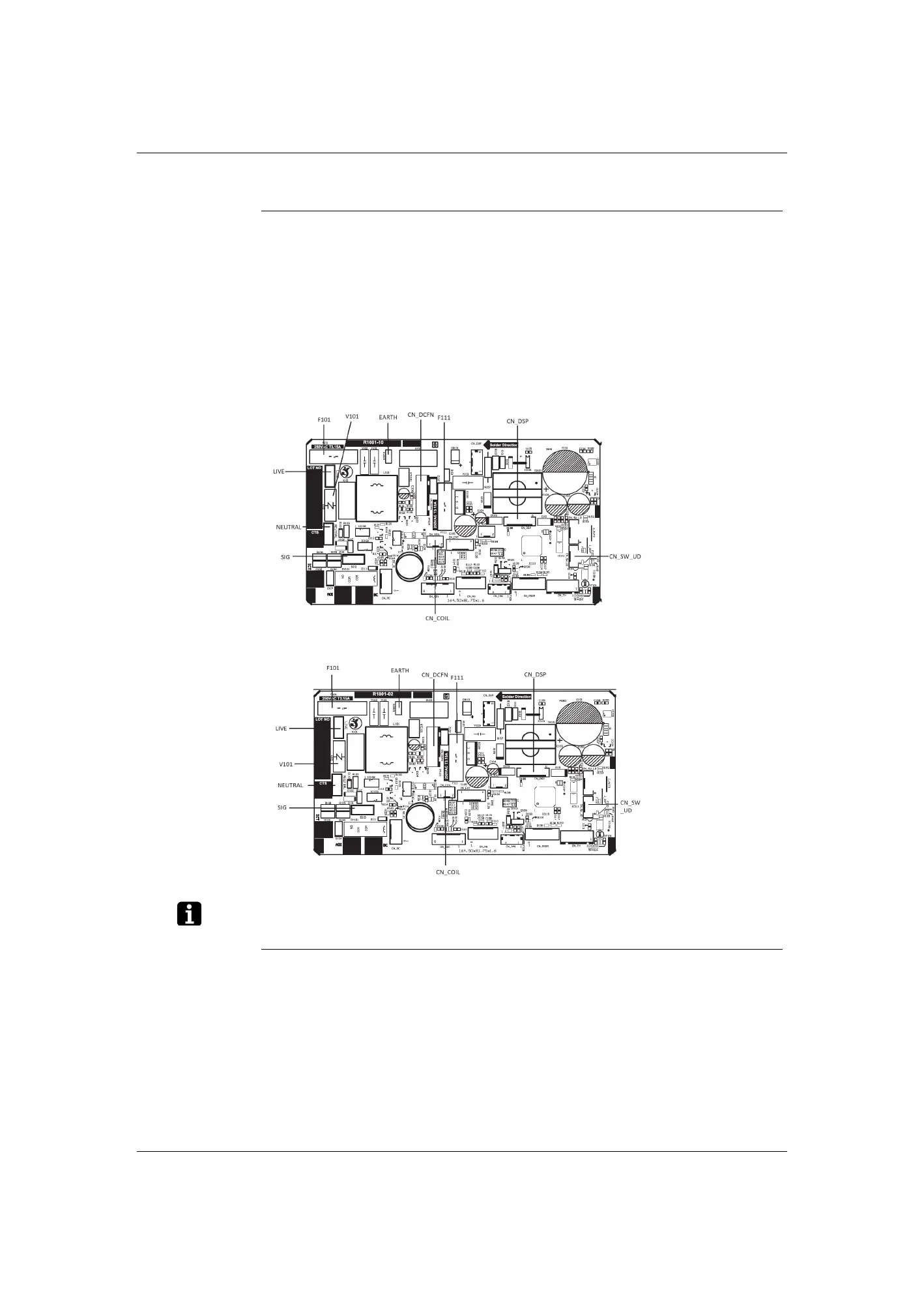
2.3 Printed Circuit Board Connector Wiring Diagram
Control PCB
(A1P)
The symbols in the parenthesis are the names on the appropriate wiring diagram.
Display/Signal
Receiver PCB
(A2P)
1) CN_SW_UD Connector for swing motor (horizontal blade)
2) CN_DSP Connector for display/signal receiver PCB (A2P)
3) CN_COIL Connector for indoor heat exchange thermistor (R2T)
4) CN_DCFN Connector for DC fan motor
5 LIVE, NEUTRAL, SIG Connector for terminal strip
6) EARTH Connector for terminal strip (frame ground)
7) F101 (F1U), F111 (F2U) Fuse (3.15 A, 250 V)
8) V101 (R2V) Varistor
1) CN_DSP1 Connector for control PCB (A1P)
2) SW201 (BS1)
Indoor unit ON/OFF switch
(Forced cooling operation ON/OFF switch)
* Refer to page 97 for detail of forced cooling operating.
3) COOL/HEAT LED (H1P) LED for operating
4) TIMER LED (H2P) LED for timer (yellow)
5 RTH201 (R1T) Room temperature thermistor
 Loading...